• Welcome to Overclockers Forums! Join us to reply in threads, receive reduced ads, and to customize your site experience!

Dumb Newbie Question on 1/2 versus 1/4 tubing

Overclockers is supported by our readers. When you click a link to make a purchase, we may earn a commission. Learn More.

Euro_Wulf

New Member
Joined
May 29, 2003
Location
Colorado
Fisrts post so want to say hello to all.

There is much discussion as to the larger diameter hoses being better than smaller dia hoses. My question is if any of the fittings or nipples used in the system or internal routing of the water path is smaller than the larger tubing would that not defeat the purpose of using a larger hose due to the restriction? In other words would it be imperative that the whole system not have a path of smaller dia then the hoses used. It would be similar to increased resistance in an electrical circuit causing a larger voltage drop but in this case a drop in flow GPH.

Also I would imagine its the gph or flow that you want maxed out not the pressure created by smaller or restricted openings.

I apologize if it seems like a dumb question but to my thinking the whole system would have to maintain the large diameter or its purpose is defeated.

Thank you in advance for your help.
 
Yes, smaller fittings, barbs and passageways than the tubes would fairly well negate the advantages of larger sized tubes.

Notice how everyone uses the same size as their tubes...
 
WELCOME TO THE FORUMS!!!!!!

There is an advantage gained by having a restriction where the water enters the block. That will increase velocity and depending on the design, will reduce the boundary layer and promote more efficient heat transfer. Most blocks that have a restriction designed into them do not depend on the barb itself though.
 
Toysrme said:
Yes, smaller fittings, barbs and passageways than the tubes would fairly well negate the advantages of larger sized tubes.

Notice how everyone uses the same size as their tubes...
Quite simply, bigger tubing = less flow resistance. But, 1/2" ID tubing mated with 1/2" barbs is NOT a true 1/2" system as 1/2" barbs are 3/8" ID. To get a TRUE 1/2" ID system, you need to run 5/8" barbs which are 1/2" ID.
 
Some information BillA gathered recently:

3-8connhlUS.gif


These are the pressure drop vs flowrate curves for pairs of barbs (and copper tubes) of varying ID.

Using SF Pressure Drop 5.0, I calculated the pressure drop for 8 feet of 3/8" ID tubing as .93 PSI @ 1.5 GPM. (About the same as a pair of 3/8" barbs with 0.24" ID.)

So, if you had a system where some component had 0.24" ID barbs, and 8 feet of tubing, there would still be substantial benefit to be had from using 1/2" tubing.

All the resistances do add up.

Edit: BTW, that tubing pressure drop I calculated was for a single straight tube, the bends in a real system would increase that pressure drop.
 
Thank you all for your responses. I found the flow rate chart very interesting.

I just have one more question please. Say u take a pump of x flow rate and just run it with x dia hoses with no other restrictions like a block or radiator etccc.,, It has x flow rate if measured on the return side. Now if u add just a block to the system and measure the flow rate does the flow rate drop off drastically measured on the return side or does it basically stay the same due to the increased velocity cause by the blocks restriction?

I guess this is basic Physics question and I know its covered in an old high school physics book I have but I can't find the damn thing. Been quite a while since the old High school days lol.

Again ty all.
 
Euro_Wulf said:
Thank you all for your responses. I found the flow rate chart very interesting.

I just have one more question please. Say u take a pump of x flow rate and just run it with x dia hoses with no other restrictions like a block or radiator etccc.,, It has x flow rate if measured on the return side. Now if u add just a block to the system and measure the flow rate does the flow rate drop off drastically measured on the return side or does it basically stay the same due to the increased velocity cause by the blocks restriction?

I guess this is basic Physics question and I know its covered in an old high school physics book I have but I can't find the damn thing. Been quite a while since the old High school days lol.

Again ty all.

The flow rate would decrease due to the increased resistance to flow introduced by the block. The water does speed up as it goes through the block's resriction, but that doesn't offset the loss of flow caused by the restriction. Think of a shower head. They have a flow that is restricted to less than what the pipe supplying it can flow, but the water that does come out has a higher velocity.

Ken
 
The centrifugal pumps commonly used for watercooling will have a pressure drop vs flowrate curve such as the Iwaki pump curves shown below.

MD_WMD_CURVES.jpg


The flowrate a watercooling system operates at, depends on the combination of the pump characteristic shown in those curves, and the pressure drop vs flowrate curve of the loop through which the coolant is being pumped.

By plotting the summed pressure drop vs flowrate for the components of the loop, and superimposing it on the pump curve, you can determine the flowrate that the pump will provide through the cooling loop.

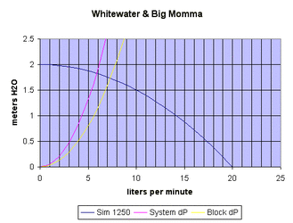
The following image shows this kind of analysis for a simple system composed of an Eheim 1250 pump, a White Water block, and a "Big Momma" heatercore. Pressure drop for tubing is ignored. (The Sim 1250 curve is a parabolic approximation of an Eheim 1250's curve, not the actual curve.)

WWandBM.gif

By looking at the point where the 'system' curve intersects the pump curve, the flowrate for this hypthetical system can be determined to be just less than 6 lpm.
 
Back