• Welcome to Overclockers Forums! Join us to reply in threads, receive reduced ads, and to customize your site experience!

Waterblock Design - Advice Needed

Overclockers is supported by our readers. When you click a link to make a purchase, we may earn a commission. Learn More.

slater3333uk

Member
Joined
Dec 8, 2002
Location
Suffolk, UK
Im trying to design a microchannel type block simlar to the whitewater but im having diffuculty finding some of the critical dimensions.

My first question is about the width of the inlet jet. How wide should this be considering i am using a eheim1250 pump? I gather this is a very important dimension and the optimal size veries with the size of pump you use.


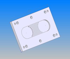
My second question is should i leave a clearance between the top of each fin and the top of the block or do they need to touch so that the water is forced to flow through the channels? I i left a clearance would this help by decresing restriction? how dose this work in the Whitewater/RBX? See the attachment. there is currently a 4mm gap between the top of each fin and the top of the block but should it be bigger smaller or none??

Im planning to use 1x1mm channels is this ok? would they be better slightly deeper?

(the base thickness will be as small as possible)

My big problem is trying to design a block that works aswell as a whitewater witout attualy copying it :bang head
 

Attachments

  • base.jpg
    base.jpg
    25.9 KB · Views: 185
From what I have heard from Cather, is that the fin/channel dimentions, base, and the jet dimmentions are very important.

I made my own waterblock, which after reading more and more about disign, it unintentionaly turned into something very similar to the whitewater without me even seeing it or knowing exactly how it was designed. I wanted to make the tallest, thinnest, fins possible with what I had to work with. I'm not sure why cathar's fins are so short (performance or time/pain in the arse). The nozzle/jet I did get from the WW. As for the dimentions... I don't know what cather used, but here's mine:

block-1.jpg
block-2.jpg
block-3.jpg
block-4.jpg

I have 9 fins total, fins are about 3/64" (1.19mm), and channels are 5/128" (1mm), and I think the fins are 3/8" tall. I used a saw blade that you mount on a manual mill and started cutting away. The fins bent as I cut the channel next to them, but I bent them back fairly straight. I think my nozzle is somewhere around 4.5mm wide x about 19mm long. Hose barbs are 5/8".

As for spacing between the top of the fins and top of the WB, I made it about 1mm... but it probably would have been better to make it close to 0, and force the water where I need it.

You want the majority of your surface area close to where the die will be giving the heat... so maybe you should make the fins longer there. Hope I helped. Try forums.procooling.com for the experts (if you haven't already).
 
Thank you Thats very helpful:)

I think the reason cathar made the fins short is because the heat cannot conduct through the copper very far. I think he said anything over 2mm away from the core was having an isignificant effect on cooling and all it would be doing was adding to restricsion. (dont quote me tho i may be wrong its been a year since i first started designing this thing)

I think the problem with long fins is that by the time the water has gotten to the bottom where it needs to be it has slowed down so much it either never gets there or is going so slow you lose cooling performance. So you make them short to get maximum water velocity closer to the cpu die.

I think i will post this on pro cooling in a mo! thanks again:D
 
DeathONator said:
I'm not sure why cathar's fins are so short (performance or time/pain in the arse).

They are short because the heat is typically dissipated long before it even reaches the tops of the short fins. Only if flow rates are really pathetically low (<< ~1 LPM) does the heat really have a chance to significantly reach the tops of even the short fins.

Under normal operation the vast majority of the heat is gone even by 2mm up the fins, with the tops of the short fins responsible for <1% of the total cooling effect. Anything more is a unnecessary, both for performance and in terms of machining time.

The secondary reason for their height is the central impingement jet, which under normal operation works best at a height of 4-5x the width of the channels. Past a height of 5x, performance of the central jet starts to degrade as the channel walls cause the jet to lose power.
 
Back