• Welcome to Overclockers Forums! Join us to reply in threads, receive reduced ads, and to customize your site experience!

Shroud Math

Overclockers is supported by our readers. When you click a link to make a purchase, we may earn a commission. Learn More.

Guderian

Member
Joined
Jun 10, 2004
Location
Ft Worth - Texas
I've been trying to come up with a shroud layout for any size radiator without using angles, due to my lack of tools.

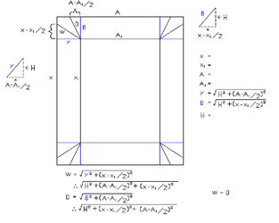
The core measures X * A

The fan mount area measures X1 * A1.

H is the height of the shroud.

Y is the length of the folded edge for the X length.

B is the length of the folded edge for the A length.

W is the length of the X side angle joint.

D is the length of the A side angle joint.

My problem lies in the final equations being equal (W = D) no matter what you put in for measurements.

I know this cannot be true unless X1*A1 is an integral percentage smaller than X*A.

In my situation, my Delta X is = 1/2in. and my Delta A is 1+1/4in.

So where is my error.......
 

Attachments

  • Shroud Math.jpg
    Shroud Math.jpg
    32.8 KB · Views: 617
Ok. I'm retarded. :rolleyes:

In my defense, I was drawing this out while working radar final control, so my brain was preoccupied.

W and D have to be equal in order to get a perfect joint.

Y and B are the important values for alignment.

So this "should" work for any setup. I will try it out with some cardboard in the near future and report back.

You will need to leave a little extra space for bends, expecially if youre making it out of metal. Add tabs on each side to slide down over the core.

If anyone sees something out of wack lemme know and I'll fix it.
 
Wow and only this morning Im being yelled at that Ill need math skills in my life.( yes im already back to school, does it ever end?!?)
 
If you want, you can get me some dimentions of what you want and I can use autocad to draw one up with measurements. if you know cad, go to a9tech.com and download a free cad program and draw up your own:)


Jon
 
so what is the equation?

Just plug in your core measurements into X and A, and plug in your fan layout measurements into X1 and A1. Decide the height you want the shroud to be and plug that in for H. Solve for Y, B, W, and D.

I recommend you do it in millimeters... makes the math a bit easier.

Draw it out on cardboard and cut.

If you want, you can get me some dimentions of what you want and I can use autocad to draw one up with measurements. if you know cad, go to a9tech.com and download a free cad program and draw up your own

core is 10 3/4 in. * 6 in (fedco 2-199 :) ) and fan "area" is currently 10 1/4 in * 4 3/4 in.

Last time I used cad was almost 5 years ago but I think I can remember how.
It'll probably be easier than doing it via MSPaint like the one above.

I'll give it a whirl tonight.
BTW, how big of a download are we talking about.....
 
Last edited:
its like 13mb not too big, its a very basic cad program, its basicly a ripoff of autocad:p

Jon
 
That was a test run.. using crappy electrical tape no less...

That one has since been retired and replaced by an identical one made from some reinforced cardboard (board game board) and, oddly enough, friction (hockey) tape and hot glue.

A temporary measure, to be sure. But I'm saving up in preparation for being unemployed in a few months for a few months.

Gah... repetitions galore in that post.
 
That one has since been retired and replaced by an identical one made from some reinforced cardboard (board game board) and, oddly enough, friction (hockey) tape and hot glue.
did you cut holes in this one? :cool:

~Magick_Man~
 
Maybe its just the fact that I like massaging parts to fit (or I never measure right :beer: 
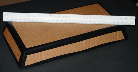
), but people using autocad for such stuff amuses me. To each his own, but when the end product is made from tin cans strung together with chicken wire... I will admit, though, it woulda saved a lot of time building my first shroud - I had put a few hours into a steel one, bent & shaped it very nicely, put it on....then noticed I wrote down "8.3 inches" instead of "9.3 inches" long :bang head

Also, don't forget to seperage the two zones inside, I recently dug up a thread on procooling talking about it - can drop temps [by a fraction] for almost no work.
 
lol, I did the same calculations for mine... Hell, I got confused every time I drew (drawed?) a line on the cardwood 'couse I did it out of a single piece (bending & cutting it), now I need to get rid of the noice/vibration on it 'couse I got it so perfectly fit/tight that the fan produces a "speaker like" effect... :bang head

PS: 4give my english ;)
 
Cool, I'll probally fallow this design and make it out of metal. Ill post links to my WC rig when its finished. (ill do a 56k BEWARE-ish post once i get my setup finished, could be 3 weeks to 4 months :( its a matter of how fast I get money and free time)
 
Hmmm. When I started to make these calculations I noticed something, It would be a LOT less annoying to do the calculations if there was an excel document to do the calculations for you. :beer:
*rolls off to make one* :burn:
 
Gads I wish I'd been taught trig. all ready. I’m in semester 1 of Algebra 2 which will have trig near the end of semester 2.

Edit: Hmm Found another guide in the watercooling stickys that combined with this make a good duo.
 
Last edited:
Back