• Welcome to Overclockers Forums! Join us to reply in threads, receive reduced ads, and to customize your site experience!

Reservoir Design

Overclockers is supported by our readers. When you click a link to make a purchase, we may earn a commission. Learn More.

NovaShine

Member
Joined
Nov 20, 2003
Location
Sydney Australia
Ok, I've bought this up in this forum a while back, but this is proboby it and im gonna take design to the plastics workers within this week (i cant mod well worth a crap and also, no tools). So here are my designs, i transferred from paper to paint cuz im too cheap to get a scanner. A few sketches couldnt be transferred cuz my paint skillz are just too crap, but i'll try my best to explain it.

This reservoir is going to be put on top of a Thermaltake Xaser III V2000A case and is meant to be a multi function piece. It is built around two JR-120 radiators, meant to hold 2 120mm fans and to keep the fans a certain distance away from the radiators to act as a sort of shroud.

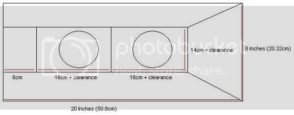
Top view:
Almost_Final_top_view.jpg

The top of the Xaser III case measures exactly 20 inches long by 8 inches wide and the reservoir was meant to cover the entire thing.

The front and sides are meant to be slanted whilst the back is one flat piece. The two circles are holes is the places where the fans can blow air out.

In between the two radiators, there is going to be a dividing piece, so that each radiator and fan combo is going to have it's own airtight box, separate from each other.

The barb positions are still not decided but i'll talk about that dilemma later.

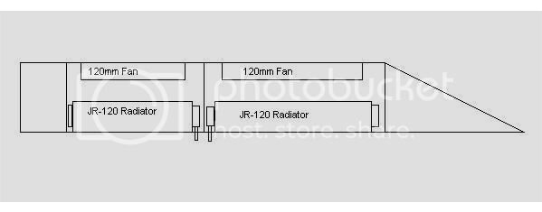
Side View (from left):
Almost_Final_side_view.jpg

This further clarifys my illustration on how the radiators and fans are meant to be mounted as well as the shape.

The fan is exactly 2.5cm tall and the radiator is exactly 2 inches or about 5cm tall. For the space between the fan and the radiator: im not sure, im thinking about 0.75 of an inch or maybe 2cm, around that ballpark figure. Anyone have any ideas about this?

So the height of the reservoir is going to be 5cm + 2.5cm + (distance between fan and radiator) + thickness of acrylic. So maybe about 10cm give or take?


Major Problem:
Where do i put the barbs?


Initially, i thought i could put them in the bottom sides, but it turned out that we were talking a width of about 2-3cm. Even if i managed to get the barb for my 1/2" ID system in, it might leave the acrylic very prone to cracking.

The length of my power supply is 14cm and the distance between the top of the PSU and the top of the case is about 5cm, so im gonna need some 90 degree elbows built into the reservoir if im putting the input and output of the res at the rear.

The length of my shortest Optical drive is 15cm and since my Hardcano that came with the case is kinda empty, the distance between the top of the optical drive and the top of the case is 5.8cm. The barb will fit if i put the barb at the front, but my hose wont bend like that.

An idea i have is maybe putting the barbs right at the back so that they're external and having the tubes lead back into the case via holes above the IO shield.

Any suggestions on this one?


Im going to be building this entire thing out of thick Acrylic. Polycarbonate is probobly out of the question, in HK, hardly anyone knows how to join Polycarbonate reliably since there's no solvent available for it here. If there is, it's probobly going to be prohibitably expensive.

Comments anybody?
As soon as it's made up, pics are going to be up.
 
A few things spring immediately to mind:

1. This is not a reservoir; a reservoir is meant to hold water. What you essentially have here is a fan enclosure.

2. In order to have efficient air flow, there should be a physical connection (i.e. a shroud) between the fan and the rad. Your current design will not act as a proper shroud due to the air space on the sides. This air space will cause undesireable turbulence. Just add a shroud to your enclosure design.

3. If the bottom of the box is where the exhaust holes are located ensure that there is sufficient space between the box and the mounting surface to allow unrestricted air flow.

4. Do not use 90 degree elbows. have the barbs come out of the bottom and travel directly into grommetted holes in the comp case. You should have plenty of space between the case and box for air flow anyway.
 
Thanks hafa,

1. It's meant to hold water too, thus, the area around the radiators, so what should we call it? resfanenclosurethingymabob? beats me...

2. Well, i guess i could have a shroud made up that attatches to the fan via screws and nuts and cups onto the radiator, that shouldnt be difficult.

3. If the radiator, fans and the top piece were taken off, the errrr (see point 1 for confusion) resfanenclosureboxthing will be hollow in the middle, the radiators basically sit on top of the case, then the boxthingy is put on top of it.

4. Elbows are a possibility, but a very remote one. I know they are very bad for flow.

Thanks for the suggestions, any more?
 
why would you want to have water surrounding your core?


i hate to say this but your design is really really in efficient and would probably cause you a lot of problems and create a lot of risk.

there is really only 2 reasons to have a res and this doesnt fill either of them.
1 a res should reduce cavitation at a pump inlet by providing maximum ability to get water into the pump .
2 it should be designed to catch air bubbles while still being able to fill the system at the same time and not increase the amount of restrictions in the system by a great deal.

just my thoughts on it
 
Last edited:
i tried to make something of that sort but as some have mentioned making it into a resevoir was kind of difficult and not very effective so i just made the thing into a radiator/fan shroud/enclosure.

here are some pics:

pic1.jpg


pic2.jpg


the whole thing is made of alumminum and there is a 1/4in neopreme gasket sealing the radiator to the top. there is a 1in gap between the top of the case and the radiator bottom, enougth space that the airflow is not restricted. In the flat area in the front of the thing I plan to make a hole to place an lcd display and maybe some switches.

the radiator can be pulled back for easy cleaning


hope this help in your design

would like to see some pics when done :clap:
 
thorilan said:
why would you want to have water surrounding your core?


i hate to say this but your design is really really in efficient and would probably cause you a lot of problems and create a lot of risk.

there is really only 2 reasons to have a res and this doesnt fill either of them.
1 a res should reduce cavitation at a pump inlet by providing maximum ability to get water into the pump .
2 it should be designed to catch air bubbles while still being able to fill the system at the same time and not increase the amount of restrictions in the system by a great deal.

just my thoughts on it

It's actually meant to hide the radiators from sight. Much of the reason for this res is for aesthetic reasons, show off some water and i'll probobly be adding some LEDs for added effect.

The res feeds directly into the pump so why dosnt it fulfil the first requirement?
I tried to avoid a T-Line cuz i dunno, i feel more comfortable with a res for some reason

Im going to make a fill hole at the rear, kinda like a milk carton top with a threaded hole where i can screw on a cap, then there's gonna be a coupler on the join with the pump outlet and the RBX, so i can drain by running the pump to get rid of most of the water, then when the water's really low, i can disconnect the pump and pour out the water. This is meant to reduce cavitation.
 
If the sides and front are too risky, maybe i can still make them, but seal off the rear end, so that it's only the rear end that's the real reservoir, but the front and sides are still going to be there. If so, i dont even need a base for it, maybe make it out of coloured acrylic...

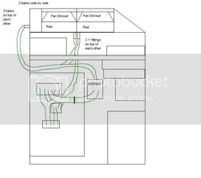
Here's a quick paint sketch of my system to be:
Map.jpg

The green lines are the tubes.
The MCP is going to be mounted vertically on the motherboard tray, horizontal to the CPU location and there's a tube from the MCP directly outputting to the inlet of the RBX, in between that, there's a coupling so i can detatch that tube in the middle easily and use it to bleed most of my system, before pouring the rest out.

My idea should get a bit more apparent as it's the back area that will be doing all the work.
The fan shrouds, as i may have mentioned earlier from an idea mentioned even earlier in this thread, is to have a pyramid like shape with no base with the top cut off, screwed into the bottom of the fan, then it splays out to encompass the radiator, much like fan adapters (eg, 80mm to 92mm).
 
Last edited:
Hey, Novashine

It appears that you are contemplating placing the enclosure/res flush with the top of the case and either taking hot air from the case or putting hot air back into the case. Take a look at this:

fanenc.gif


By using a push-pull configuration, you'll get more air with less noise, and by porting the air in from the front of the enclosure, you'll get nice, cool air over your rads, use normal convection (hot air rises) to enhance airflow and have a cool looking (scoop) on your enclosure.
 
Does cool air from outside make a difference? You definately got me listening, but since i got the biggest heat sources watercooled, there wont be THAT much heat in the case right? Going to be having 2 Panalfo H1A 80mms in the front intake, 2 stock orange TT fans in the back exhausting and 2 38db 80mm clear blade fans on the side intake and a 120mm Aluminium Evercool floor intake.

One of the biggest goals for this watercooling project is to have a much lower volume of noise, whilst having a much better cooling system. Wont 4 fans in the top really make alot of noise? Can't it be done with 2 single fans? I cant get any good 120mm fans here in HK, i have to order them from the states and it gets expensive and annoying :(.

Anyway, can you give me more details on how the piece can be elevated for an intake? Im thinking of reusing the original design, but having it elevated up, then having the front slanted a bit more and have the sides open?
Is it going to be that much of a difference?

Oh, and the rads are going to be exhausting.
 
Even though you'll have adequate ventilation in your case, the temp will be higher than ambient. Since you are embarking on an original design, every feature you can integrate into that design to boost efficiency should be adopted.

Rather than elevating the box for an intake, simply take your existing design, make it taller and cut out a slot in the front bottom for air intake. Another advantage to this is that you can incorporate a filter into the intake slot to minimize dust.

Hope this helps
 
The res feeds directly into the pump so why dosnt it fulfil the first requirement?

1 a res should reduce cavitation at a pump inlet by providing maximum ability to get water into the pump .
your res design does not make it easyer for your pump to get water than it would be without the res.

you see you would just be putting a normal line in to the pump intake which isnt any diferent than 99% of the other rads out there. . if you want to improve it make the outlet that goes to pump intake much larger than your standard tubing and change the intake barb fittings to a larger size.
an example of this is the res and pump mods im currently working on.
http://www.ocforums.com/showthread.php?t=304818

check out how the water is less restricted . personaly if your going for looks then oyu dont have to make the top part . your res at all but make a T line instead and just seal the water in your design seperately.
 
Back