- Joined
- May 7, 2004
- Location
- Eastern Pennsylvania
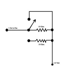
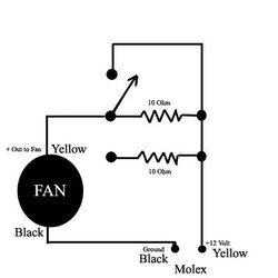
Im planning on using 2x 120mm fans outside the case using a 12 volt 1500ma ac/dc converter. The fans are 12volts .52 amps. I want to be able to switch the fan from 12v to 9 to 7.5v using a 4 position switch. I want to use resistors for the power drops and not a rheobus. I know I will need an 8ohm and 6.8ohm resistor.
The question...... Im not sure what wattage I should get. Calculations said I will need something at least 5 watts but the ones at radioshack are only ¼ ½ and 10 watts. Would a resistor rated to 10 watts affect the resistance? If so where could I get one at 5 watts? I went to mouser.com and there were soooooooooooo many options it just confused me.
Also thinking about undervolting a D4 waterpump if its too loud for me at night so this would help with that as well.
Any help would be appreciated.. Thanks
JT