• Welcome to Overclockers Forums! Join us to reply in threads, receive reduced ads, and to customize your site experience!

LED wiring assistance needed

Overclockers is supported by our readers. When you click a link to make a purchase, we may earn a commission. Learn More.

IFMU

The Xtreme Senior Nobody
Joined
Jun 21, 2001
Ok, as the title states, I need some LED wiring assistance needed.
I will be running about 20 or so LEDs and from what Ive gathered here I will need to run them parallel.
I will also need to wire in a switch that has 3 prongs on the backside. The switches are labeled 12v and I would like them to light up when they are off.
So, how do I wire them? Please explain the very basics, I dont know much about wiring LEDs or even switches that much. The LEDs I will be using are the ones that greenman has for sale in the classies.

So, can anyone help me out here? I can answer any questions anyone may have.

TIA

IFMU
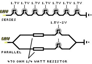
 
parallel would be simplest and would allow you to run them at the voltage closest to their operating spec. Have you already purchased the LEDs and did they include the resistors you need for 12V?

I'm on AIM now

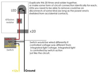
In parallel you run new wires for each LED with a single resistor for each LED. To toggle all your LEDs on or off, simply wire a switch as a stop-gate on the positive leg of the parent circuit for all the LEDs.
led.jpg

I made a simple diagram for you:
led_ifmu.jpg
 
Last edited:
Thanks for the help CS. The pic helps some, but I dont understand a couple things on it.
1st is the "circuit connection" ? what does that mean?
2nd is on the switch, you have 4 outs on the back, my switch only has 3?

led_ifmu.jpg
 
Sanyote said:
How are you mounting them? On a PCB or on a panel?
Neither.
I want to run about 20 LEDs about 5 to 6 inches apart along the backside of the motherboard. To back light the board and to light the case.
Then I will be running 20(ish) UV LEDs on the side panel along the side the window to cast the UV into the case to outline UV designs I want to do inside the case.
 
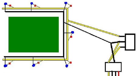
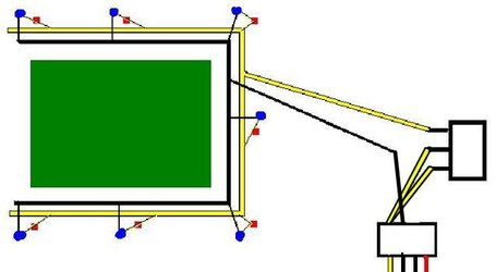
Ok, Ive tried to draw up what I think is the way to do it. Looking at that site and the pic you made up.
Key for the drawing.
Green box, motherboard.
Molex on the bottom right.
Switch just above that.
Yellow lines with Black border 12v line
Solid black line ground
Blue circles are the LEDs
Red Boxes are the resistors
So, by the drawing, is that right? Would that work?
 

Attachments

  • 1.JPG
    1.JPG
    20.8 KB · Views: 74
IFMU said:
So, by the drawing, is that right? Would that work?

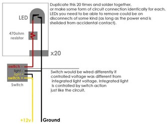
Everything is correct except that the +12v should be the only thing wired to the LED indicator on the switch. DO NOT WIRE THE GROUND TO THE LED indicator terminal. Do it like this.
led_ifmu2.jpg
 
Gotcha.
Thanks for the help!
 
Back