• Welcome to Overclockers Forums! Join us to reply in threads, receive reduced ads, and to customize your site experience!

Made my own DDC acrylic top- How & Pics

Overclockers is supported by our readers. When you click a link to make a purchase, we may earn a commission. Learn More.

voigts

Member
Joined
Feb 11, 2005
Location
Tennessee
Well, being the cheapskate and ardent do-it-yourselfer, I decided to give it a try at making my own DDC acrylic top. This is an intended modification that I am going to make to my custom wood case setup (http://www.ocforums.com/showthread.php?t=449069&highlight=design+reality).

Instead of doing the flow mod, I wanted to make a top that would allow for a 5/8" inlet and 1/2" outlet (I like to use 5/8" barbs when possible since I am using 1/2" tubing). Also using a top would allow me to return the pump should it ever fail vs. doing the flow mod.

I got 7- 4"x4"x1" cast acrylic blocks off of ebay ($20 total shipped). I wanted to make a top that would model somewhat off of the radiical.com.au top (http://radiical.com.au/products/RadiicalPumpTop.asp), but I don't have the $50 at present to sink into one.

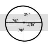
First, I measured the original DDC top for the inside diameter and depth. It has a slight spiral to it. So I drew the thing in Photoshop to use as a template for my top:

HoleTemplate.jpg

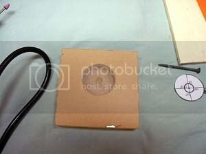
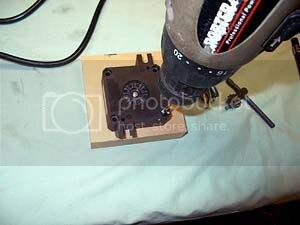
Then I eyeballed where i wanted it to go, traced the outline and centerpoint onto the acrylic, and drilled a 1 1/2" hole into the block with a drill press. This is the largest sized boring bit I can find anywhere.

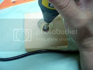
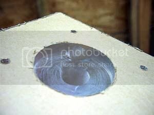
I then had to ream out for the spiral effect. I used my trusty Dremel imitation Nikota rotary tool to sand out the edge to the line that I had marked.

IM000049.jpg

IM000051.jpg
 
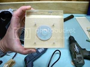
Having looked well at the radiical.com.au pics, I could see that I needed to get my mounting holes drilled before drilling the outlet hole to make sure I didn't drill the outlet hole through a mounting hole. I took the pump and positioned the head where I wanted it so that it has the same clearance of the original top, flipped it over while holding it in place, and partially drilled the four mounting holes just enough to mark them.

IM000052.jpg

IM000053.jpg

I then went ahead and used my drill press to drill the 9/16" hole I needed for the inlet, making sure to ream it out a bit to make it easier to tap later.

IM000055.jpg
 
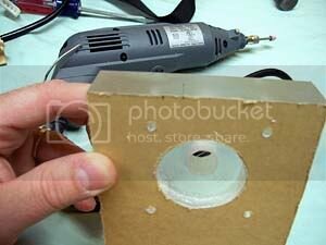
Then it was on to drilling the outlet hole. I marked this one to get it as close to the bottom as I felt comforable with and enough away from the mounting hole so as to not drill through it.

IM000056.jpg

I again needed a 9/16" hole for the threads for the barbs. The only 9/16" drill bit are wood boring bits which have a long pointy tip. I realized that I only needed to drill in with the 9/16" deep enough so that I could tap the hole. I didn't want to go too deep with it however as the tip would penetrate too far into the block. So I first drilled as far as I measured I needed in order to tap out the thread, and finished the hole with a normal 1/2" drill bit, drilling just enough to break into the interior area. 1/2" is as big as normal drill bits usually come. I just reamed out the end a bit with it.

IM000058.jpg

IM000057.jpg
 
Drilling too deep into the block even with the 1/2" would have left a kind of drop off from the pump head drilled out area going out to the outlet. So like I said I just drilled enough to break into the interior pump head area, and from there the Nikota rotary tool was my friend. I copied the look of the original top to make a smooth channel to pass the water from the head to the outlet. This took some shaping and sanding to achieve, but it worked great.

IM000064.jpg

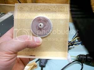
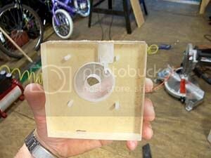
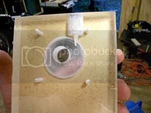
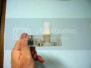
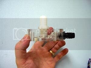
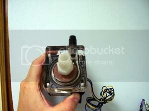
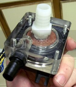
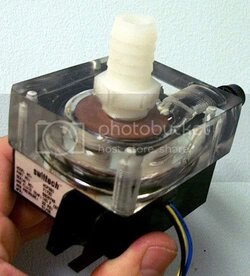
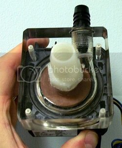
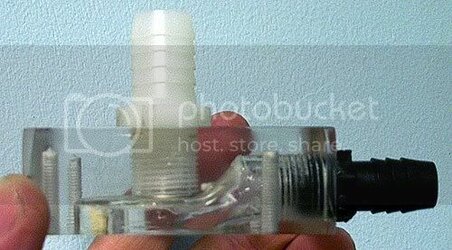
After more shaping and some sanding and trimming the block to size with a compound mitre saw and flame polishing, here is the final product.

IM000070.jpg

IM000068.jpg

IM000067.jpg
 
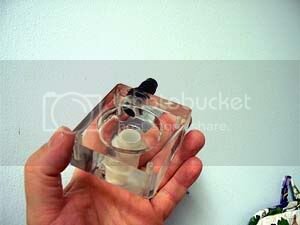
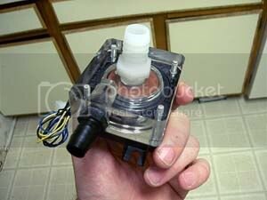
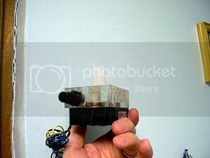
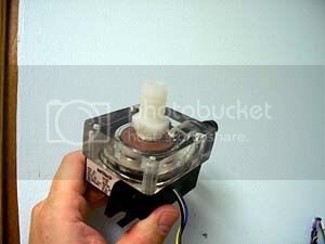
And here it is mounted:

IM000074.jpg

IM000073.jpg

IM000072.jpg

IM000071.jpg

I haven't flow tested it yet as I just finished it today. This block is the second version. The first one turned out, but just wasn't quite happy with it and so made a few changes to make this second one. I am very satisfied with this second block.

I already have the drill bit, rotary tool, and most bits that I needed. I only had to get a bit and some sanding disks. So all in all it took me a couple of hours to make and cost me about $10 to make.

Maybe this will inspire others out there...
 
Nice

I really wish a company would consider making a low cost delrin top for the ddc. I think i am going to try to make a top to accomidate two ddc's over the summer, but for now i will stick with my iwaki.

Its great seeing a bunch of homemade stuff. First the copper cap blocks and now this.

Is that the rev 2? Will u be using a single ddc or two of them?


edit: deleted previous post and made this one since the other one interupted voigts' posts.

edit2: do you have any bigger pics of it. The craftsmanship looks great, but the pics are pretty small. Awesome job.

edit3: deleted yet again so that i would no interupt voigts' posts

edit4: :p why do i have so many edits?
 
nachosyumm said:
Nice

I really wish a company would consider making a low cost delrin top for the ddc. I think i am going to try to make a top to accomidate two ddc's over the summer, but for now i will stick with my iwaki.

Its great seeing a bunch of homemade stuff. First the copper cap blocks and now this.

Is that the rev 2? Will u be using a single ddc or two of them?


edit: deleted previous post and made this one since the other one interupted voigts' posts.

edit2: do you have any bigger pics of it. The craftsmanship looks great, but the pics are pretty small. Awesome job.

thanks. I was smack in the middle of posting this when you wrote. yes, the pump is the 18w. My goal is silence, so I actually ordered what I thought was a 10w but received an 18w instead. I think at this point I am probaby just going to live with a few more decibels over the 10w and keep it. I am only going to be running the one pump as two pumps is just more noise and not much more performance wise. I care more about quiet than performance.

I can post a couple of bigger pics if you want me to.
 
yay, much better. Thanks. You always seem to use really small pictures.

It was hard for me to really see the finished piece with 1024 x 768. Do u use a small monitor?

wow, that seemed to work out perfectly. I cant wait until you get some tests done.
 
nachosyumm said:
yay, much better. Thanks. You always seem to use really small pictures.

It was hard for me to really see the finished piece with 1024 x 768. Do u use a small monitor?

wow, that seemed to work out perfectly. I cant wait until you get some tests done.

No, I use a 19" at 1280x1024. I just try to avoid huge pics for those unfortunate who are stuck with dial-up access.
 
Last edited:
Very nice handiwork, voigts! :attn:


nachosyumm said:
I really wish a company would consider making a low cost delrin top for the ddc.

Get out of my head. :p I was thinking something similar and e-mailed a request for such to a popular watercooling supply company. They replied with something like: "That [removing the 90 degree inlet] would lower the output pressure while increasing the flow. You would be better off with the [their version of the D5]. :shrug:
 
Jeez V, you work fast.
Wasn't it just yesterday morning we were talking about this project?

Should be interesting to see what sort of performance your new design provides.

I assume your next project will be carving a CPU out of oak or something....
 
Really nice. On the start i didnt know what was the top for, but then i saw the bigger pictures and i saw it was for the pump. :)
 
Very interesting, Voigts, and beautiful work! :beer:

How close do you think your impeller chamber is to the original? I've been thinking about how to make a mold to cast a top with a larger outlet, but I've been a little worried about the tolerances. I don't really know much about pumps, and I don't want to goof in a way that causes something to wear out. :bang head
 
Thanks for the positive comments.

clocker2 said:
Jeez V, you work fast.
Wasn't it just yesterday morning we were talking about this project?

Should be interesting to see what sort of performance your new design provides.

I assume your next project will be carving a CPU out of oak or something....

BTW- the guy you mentioned did have 1 more radiical left, but I already started making this before he emailed me back so I figured I would just plow ahead and make it. I am taking a few days off of work due to a bad knee + pulled groin muscle + sudden change in weather=pain, so I had some time to mess with it.

Now, if I could only find that block of oak I was looking for I would be the envy of both AMD and INTEL. :)

Otter said:
Very interesting, Voigts, and beautiful work! :beer:

How close do you think your impeller chamber is to the original? I've been thinking about how to make a mold to cast a top with a larger outlet, but I've been a little worried about the tolerances. I don't really know much about pumps, and I don't want to goof in a way that causes something to wear out. :bang head

By using a template that I measured from the original chamber, the chamber I made is as close to the same dimensions as is possible. I even made the depth of the chamber the same (almost 5/16"). In visually comparing the two with the pump head, they look the same and measure the same. The only notable difference is of course that mine is not PERFECTLY rounded as I did sand to achieve the spiral effect.

I'm not sure that the tolerances are really that big of a deal. Although I didn't see the radiical block, Clocker2 has one and mentioned that the chamber of it is round, not spiral, which if that is the case, then a little difference shouldn't matter too much.

How exactly would you go about casting a top anyway?

TreeNode said:
How did you dremel the screw/barb holes? BTW, it looks nice!

The barb holes were drilled with a 9/16" wood boring bit using a drill press, and for the outlet hole, I finished the hole with a normal 1/2" bit and reamed it out a bit to match the 9/16" hole.

R B Customs said:
beautiful piece of work mate
could you go into detail about fexactly how you plished it ? only ill be doing alot of work in acrylic soon :)
thanks for posting
Rick

Knowing that I was not gluing anything with this block, I could sand with a sander and flame polish. You can't do that if you are gluing to an edge as it will cause it to craze (I have found that if gluing, you can only sand by hand). I simply sanded the edges and insides as smooth as possible with a variable orbit sander and my Nikota rotary tool, and then used a MAPP gas plumbing torch to flame the edges and interior. I have never done this before, but it is really pretty easy. Using a MAPP gas torch works very well as it burns very hot and only takes light touches with the flame to make the surfaces shine. I just used the torch to touch the places I wanted to polish (after sanding) with the flame briefly a few times until it shined to my liking. This slightly melts a bit of the surface and takes out minor imperfections as well.


Now I have got to figure out a good way to flowtest this. Anyone got any ideas?
 
Last edited:
Back