-
Welcome to Overclockers Forums! Join us to reply in threads, receive reduced ads, and to customize your site experience!
You are using an out of date browser. It may not display this or other websites correctly.
You should upgrade or use an alternative browser.
You should upgrade or use an alternative browser.
Two power supplies - How to turn on at same time?
- Thread starter Raizy
- Start date
- Joined
- Jun 16, 2006
http://www.ocforums.com/forumdisplay.php?f=42
start looking there. thats the psu and case section. this question has been asked and awnsered a few times.
start looking there. thats the psu and case section. this question has been asked and awnsered a few times.
- Joined
- Jun 16, 2006
np. Welcome to the forums.
- Joined
- Jun 11, 2004
Here's a couple good articles on dual PSU's.
http://www.speedy3d.com/articles/case_mod_p3/index.shtml
http://www.burningissues.net/how_to/power/psu.htm
I wouldn't recommend using the method where you modify a 20-24 pin adapter harness these days. Current CPU's need so much current that even slight resistance in the supply wiring can cause a significant voltage drop. Hence, you don't want any extra non-soldered connections between the PSU and the mobo.
- Joined
- Apr 19, 2003
Otter said:Here's a couple good articles on dual PSU's.
http://www.speedy3d.com/articles/case_mod_p3/index.shtml
http://www.burningissues.net/how_to/power/psu.htm
I wouldn't recommend using the method where you modify a 20-24 pin adapter harness these days. Current CPU's need so much current that even slight resistance in the supply wiring can cause a significant voltage drop. Hence, you don't want any extra non-soldered connections between the PSU and the mobo.
Erm... Voltage drop does not depend on the current travelling through the conductor with a given resistance.
khriez said:You said unsoldered, so does that mean it would still be okay to solder the 2nd power supply green wire to the first by cutting the wire?
From an electronics standpoint yes, soldered connections will be fine.
I haven't done much with dual PSUs however an easy way to do it would be to have an unused rail from the PSU hooked up to the motherboard activate a relay that would connect the neccessary wires on the second psu, turning it on. That's the way I'd most likely go about it, but it might not be the best. *Shrug*
- Thread Starter
- #8
sendatooli said:... i cannot afford a fire!
now i know if done right a fire is unlikely. i also have a decent knowledge of electronics. the diagrams are very straight foward.
however, anything that can go wrong will. this could prove dangerous even if done "right".
i did not mean to spoil the party. i am just glad i read the fine print that allowed me to make my decision.
Damn... how safe is the guide in the speed3d link? The one where you use a relay ? How would a fire start? I need to know why a fire would start -- so I can find a solution... TRIPLE PSU'S BABY!!!!!!!!!!!
- Joined
- Apr 19, 2003
khriez said:Damn... how safe is the guide in the speed3d link? The one where you use a relay ? How would a fire start? I need to know why a fire would start -- so I can find a solution... TRIPLE PSU'S BABY!!!!!!!!!!!
I didn't *want* to have to read one of those but I just skimmed one

Just as I suggested, use a relay to connect one of the green leads to the black on the second PSU and use an unused rail to power the relay.
Heh, funny. Hadn't ever thought about doing dual-psus but that guide is pretty much exactly what I imagined
As to safety it's just as safe as running a single PSU. I'd make sure to keep things tidy and avoid shorts. Fire wouldn't be any more likely than running a single PSU.
That's the way I'd do it, to be honest.
-Ex
- Joined
- Jun 11, 2004
Sure it does.Excelsior said:Erm... Voltage drop does not depend on the current travelling through the conductor with a given resistance.
V=IR
Double the current, and you double the voltage drop.
- Joined
- Jun 11, 2004
Yes. In fact, you could just use wire nuts or for that. The green wire doesn't carry much current. What you want to avoid is putting non-soldered connections into the circuit that feeds the CPU.khriez said:You said unsoldered, so does that mean it would still be okay to solder the 2nd power supply green wire to the first by cutting the wire?
Cutting the wires on your main PSU might be a problem if you ever need to RMA it, though. If you want to preserve the warranty, use a relay.
Here's an old pic I made.
Notice the switch, that's to turn on the secondary supply without the first, so you can bleed a waterloop w/o the mobo on, or maybe eject a CD after shutdown (needed that a few times ).
The switch is a simple two contact on/off switch. The green and blacks just connect to the terminals and continue on their way to the relay.
You can use a fan>molex splitter between the 12v/12v relay (pictured is the black cube shaped one at radio shack) and the first power supply so that you don't need to cut the main psu's molex wire and keep it's warranty alive.
Of course the other wires on the psu's aren't in the pic. Just use them all how you want.The main psu pictured is for powering the motherboard though.
 to the forums!
*Oh, and for you nut cases out there, the same would work for multiple psu's as the amperage rating on that cube relay is plenty high enough. Just hook all the secondary psu's green/black's to the same place. You can use those crimp on female spade connectors for the relay too, as it has the male spade's.
**Using ONE switch on ONE of the secondary psu's will power on ALL the secondary psu's though.**
Notice the switch, that's to turn on the secondary supply without the first, so you can bleed a waterloop w/o the mobo on, or maybe eject a CD after shutdown (needed that a few times
).The switch is a simple two contact on/off switch. The green and blacks just connect to the terminals and continue on their way to the relay.
You can use a fan>molex splitter between the 12v/12v relay (pictured is the black cube shaped one at radio shack) and the first power supply so that you don't need to cut the main psu's molex wire and keep it's warranty alive.

Of course the other wires on the psu's aren't in the pic. Just use them all how you want.The main psu pictured is for powering the motherboard though.
to the forums!*Oh, and for you nut cases out there, the same would work for multiple psu's as the amperage rating on that cube relay is plenty high enough. Just hook all the secondary psu's green/black's to the same place. You can use those crimp on female spade connectors for the relay too, as it has the male spade's.
**Using ONE switch on ONE of the secondary psu's will power on ALL the secondary psu's though.**
Last edited:
- Thread Starter
- #13
Cool, one more question (I should be asking this in the dual PSU sticky -- but this thread seems more active).
Let's say a Power Supply has 18Amps max on the 12V rail. A peltier requires 18W from the 12V rail, but you are thinking about powering up a 12V water pump that wants 8-12Amps -- it is not possible to power up these two components on a single PSU.
Since the total amps required from the 12V rail exceeds 18Amps, in this case water pump+peltier totals 26-30Amps.
Correct?
Well first, the D5 pump only takes < 2 amps on high (20 watts is it's rating I found on D-Tek's site).
I wouldn't run an 18 amp peltier with an 18 amp computer psu. It will most likely overheat and shutdown. You need to have some headroom, and most computer power supplies will not actually output their rated maximums for very long, save for the more expensive ones like Seasonic, PC Power & Cooling and the like.
If you must, use a power supply with either combined rails (where it says there's two or more but they're actually only one) or one with 24+ amps.
You could also use a pair of wires from each of two rails. It would be best to use it that way anyway because the skimpy 18 gage wire is pretty small for that many amps.
For a peltier cooler, it's best to suck it up and get a nice Meanwell power supply in the 24-30 amp range. Then you can power a pelt and the pump on the same psu.
I haven't used a Meanwell before, and am not sure if you can power it on with a relay, or even if you'd want to...if memory serves, it's best to have the peltier fired up and cold BEFORE the cpu gets power. The peltier gets cold slightly more slowly than the cpu would get hot when you turn it on.
The guys in the "Extreme Cooling" section would be better equiped to help you here though, it's been a few years since I dabbled with pelts and my info will not be so up-to-date.
- Joined
- Jun 11, 2004
Folks from extreme cooling crowd commonly say that phase change is less of a hassle than TEC's. It's also more energy efficient, and if something goes wrong with the system, at least it won't add heat to your CPU.khriez said:Damn a peltier was more trouble than I thought...oh well good thing they are only 30 bucks.
I've read that if you power something from two different PSU's in parrallel, most of the load will go to one PSU until it maxes out. That's fine as far as the component that's connected to both supplies goes, but it might be a problem for anything else connected to the PSU that's running at 100% power. It will also shorten the life of the PSU doing most of the work and cause more PSU fan noise than you'd get with a balanced load. I'm not sure how this applies to a load across two rails of the same PSU, but I suspect you'd see the same problem.
- Thread Starter
- #17
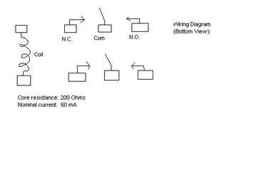
I am having trouble wiring this 8-pin relay.
I followed the guide in speed3d.com link in the sticky for the relay guide.
The wiring diagram behind the package label looks like that one in the pic attached.
When I press the power botton only my main PSU powers up and the 2nd one doesn't do anything.
I followed the guide in speed3d.com link in the sticky for the relay guide.
The wiring diagram behind the package label looks like that one in the pic attached.
When I press the power botton only my main PSU powers up and the 2nd one doesn't do anything.
Attachments
- Joined
- Jun 11, 2004
If I understand the diagram correctly, you want to connect the molex from the main PSU to the pins marked "coil". Connnect one of the black wires from the slave PSU's motherboard connector to "COM".
The green wire goes to "N.O." (normally open). When the Main PSU comes on, the coil closes the switch to connect "normally open" pin to the common pin, and your slave PSU should power up too.
If you're switching the 120V line in instead of the "PSU On" line (green wire), the grooved or striped wire or wide blade from the second PSU's power cord goes to "COM" (common/neutral), and the smooth wire or short blade goes to "N.O.".
- Thread Starter
- #19
AHh thanks for that, I i think I broke my power supply making random solders lol. But I just unplugged it and plugged it back in and it works now. What is an indication that the power supply turned on and shut off right away, and then the computer wouldn't turn on? Not sure what kind of damage I did... but it's worknig right now so I hope it's okay.
--------------
I have a 10 ohms and 33 ohms resistor rated at 1W. When I short out the red wire (on the old PSU the multimeter reads 2.83V -- I thought red wires were +5V) the resistor gets REALLY hot. Am I suppose to connect the resistor into the red pin and the black pin? Or am I suppose to just connect it to a red wire and nothing else ?
Similar threads
- Locked
- Replies
- 3
- Views
- 176
- Replies
- 0
- Views
- 397