• Welcome to Overclockers Forums! Join us to reply in threads, receive reduced ads, and to customize your site experience!

Work In Progress: "Anubis"

Overclockers is supported by our readers. When you click a link to make a purchase, we may earn a commission. Learn More.

Paltiel

Registered
Joined
Dec 29, 2007
Location
Noo Joisey
Anubis_01%20-%20Front.jpg
Anubis is named after the Egyptian God that's a guardian of the dead. Why Anubis? I don't know; My wife's an artist, she picked it, please go ask her. ^_~
I'm just the grunt building the beast for her.

Anubis will be used for solid object modelling and rapid prototyping, so we needed a dual-CPU motherboard and tower case that will fit it. It essentially needs as much processing power as we can throw at it. Since my wife is both an artist and a scary FPS gamer - she shames me all the time in Quake T-T - we also planned on using video cards in SLi.
Two CPUs, an eATX motherboard, two video adapters, and an SAS hard drive would have been much too loud with pure air cooling. Liquid-cooling wasn't so much a possible choice as much as it was a need.

My background is that of an engineer - specifically electrical and computer science. I can also wield a Dremel.

Apart from simply working, I also wanted Anubis to look good. That meant sleeving exposed wires with non-conductive reflective plastics, using straight lines whenever possible ( flow rate be damned ^_^; ), hiding wiring, and internal lighting. A note about the lighting: There's a three-way switch in the back of the case that lets us select between UV lighting, visible blue lighting, or no lights. Power to the lights are controlled remotely via a hand-held fob. Think of a wireless keyless entry system on a vehicle - that's exactly how it works.

Components installed thus far:

Case: Thermaltake Armor

Motherboard: SuperMicro H8DAi-2 (Double Quad-core Opteron capable)

Radiators: HardwareLabs
1 - Black Ice GT Stealth X-Flow 120mm (Blue)
1 - Black Ice GT Stealth 120mm (Blue)
1 - Black Ice Micro 80mm (Blue)

Reservoirs: Danger Den
2 - Acrylic Clear Reservoir

Pumps: Laing
2 - DDC 3.2 18W pumps

Pump tops: Radiical
2 - Turbo Head Series 3 Pump Housing For Laing DDC-3.2 12 Volt Pumps

Fan controllers:
1 - Zalman ZM-MFC2 with power usage monitoring
1 - Logisys Silver 3.5 Inch LCD Thermal Controller (FP206SL)

Fans:
1 - Everflow 120mm PWM Fan (R121225BU)
2400 R.P.M. Maximum @ 110 CFM (39.5 dBA)
1500 R.P.M. @ 66 CFM (30.5 dBA)
1 - Evercool AL12025
2000 R.P.M. Maximum @ 79.1 CFM (30 dBA)
1 - Evercool 80mm AL8025B
2500 R.P.M. Maximum @ 32.4 CFM (25 dBA)

Fillport: Koolance Coolant Fill Port

Flow meters: Koolance
2 - Coolant Flow Meter (INS-FM16)
2 - Flow Meter Power Adapter (ADT-FM002K)

T-connectors: Danger Den Acrylic G1/4 T-connectors

Plugs: Bitspower
4 - G 1/4 acrylic ("crystal") plugs

Thermal sensors: Cooler Master
4 - Thermal Sensor Cable

Compression fittings: Koolance G1/4 1/2" I.D. 5/8" O.D.

Drainport:
1 - Dental Equipment Parts Quick Disconnect Coupler with Shut-Off (Part #09-0044-00)
1 - Dental Equipment Parts Quick Disconnect Insert without Shut-Off (Part #09-0032-00)

Syringe: Danger Den Filling Syringe

Wire guides: Zip tie hold downs - The Home Depot is your friend

SAS Cables: OKGear 10" SATA-II Cable - Clear Silver (GC10ATASM)

Combo SATA & Power Cable: OKGear 14" Silver SATA Cable and Power Combo Plug (OK105 Silver)

Slot protectors: Lamptron UV Blue Slot Protector for RAM, PCI, & PCIe slots

Light remote: Logisys 12V 15A/6A Relay W/ Remote Control (RM02 or RM01)

Power converter: AsiaEngineer DC OR AC to DC 5V Converter

Lights:
2 - Logisys 12" Day and Night Blue/UV Interchangable CCFL Kit (CLK12ST2)
4 - Danger Den 5mm UV LED tailed

Worklog notes:
- Danger Den fillports are too tall to fit underneath the Armor's bonnet
- The Koolance flow meters are designed to work with motherboard/fan controller RPM monitoring inputs. 1 liter per minute of flow is equal to ~1,000 R.P.M.
- Two of the Danger Den UV LEDs burned out. One died within ten minutes of connection, and the other died after about a week. Total usage on the second one that died was less than ten continuous hours...
- Thermaltake T-Type Water Temperature Indicator (CL-W0033) while able to accept 1/2" I.D. tubing, are much too restrictive internally, ridiculously restrictive in fact.
- Koolance G 1/4 fluid thermistors have much too high an internal resistance to correctly be read by standard fan controllers.
- January 9 2008 update: Added pump and pump top information
- March 16, 2008 update: Added motherboard, SAS/SATA cable, and slot protector information

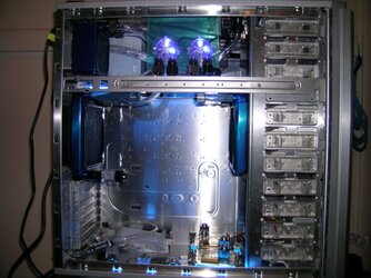
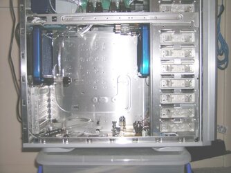
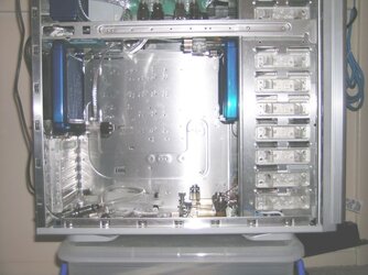
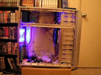
Two of the radiators have been installed, both in a "pull" fan configuration. Four UV LEDs are lighting up the two reservoirs. Eventually, there will be an exhaust duct connecting the 120mm radiator on the right to the front of the case. The blue LED fan will also be replaced with a PWM fan that can pump considerably more air. Wires are everywhere - it looks much too messy. I plan on drilling a hole in the bonnet atop the case to install a fillport. An automatically-sealing drainport will be installed at the bottom left of the case.
Anubis_02%20-%20Side.jpg


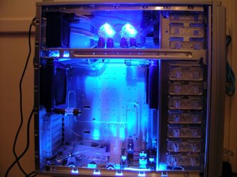
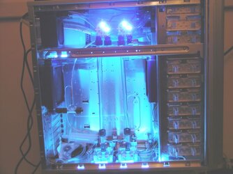
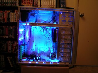
Here's an action shot with the lights powered on. The CCFLs have been hidden behind support bars so that they only illuminate the case, and don't cause blindness. Double-sided velcro holds the upper lamp in place, and simple tension secures the lower one.
Anubis_03%20-%20Side.jpg


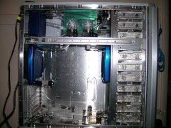
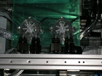
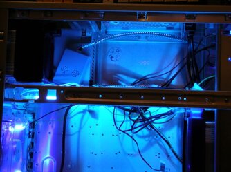
Here's a close up of where the flow meters will be installed.

I plan on cutting openings shaped like the flow meters' outlines in a polycarbonate ("Lexan") sheet and suspending the sheet, with the flow meters inside, from the top of the case.
Anubis_04%20-%20Side.jpg


This is our inexhaustible, fully redundant (two cheek pouches!), 1.2 kilowatt power supply, Lina. She's walking away, unhappily, because we decided that we're not going to use her to power Anubis.
Instead, I plan on using a single-rail 1KW PSU from PC Power & Cooling. The power supply currently inside the case is an old 200W clunker. It provides power solely for testing the lights.

Anubis_05%20-%20Power%20Supply.jpg


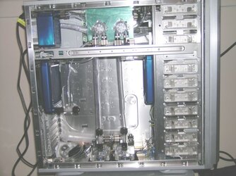
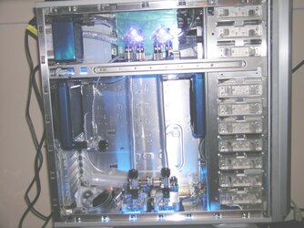
Wire management has been completed and all but one fan wire, one PSU wire bundle, and the power monitoring cable have been sleeved. The power monitoring cable has been moved to the top of the case - look at the cord with the yellow tab at the top left of the image. The exhaust duct has been installed on the radiator on the right side, and the flow meters have been connected to their controllers.

The flow meters are currently sitting on the bottom of the case. They've been configured to strobe based upon the flow rate of the fluid; greater flow means more frequent strobing. Acrylic T-connectors and temperature monitoring thermistors have been connected inline with the radiators and reservoirs. A couple of tubes have also been installed. The tubing is for sacrificial purposes only, it's Clear Flex brand from the local Microcenter and it'll be used for measuring how much real tubing is needed. I plan on using Tygon brand tubing in the finished system. Some cautioning words of note: the Clear Flex tubing kinks much too easily.
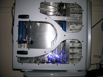
Anubis_06%20-%20Side,%20outside.jpg


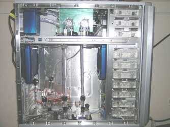
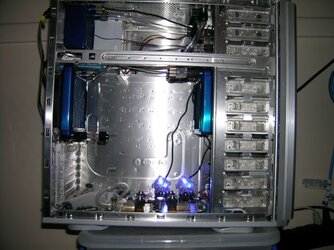
Here's the same view with the side panel removed. The black cable at the top is the power monitoring cable.
Anubis_07%20-%20Side.jpg


Here's a close-up of the fill-line attached to the fillport and also the tube leading from the topmost radiator to the topmost reservoir.

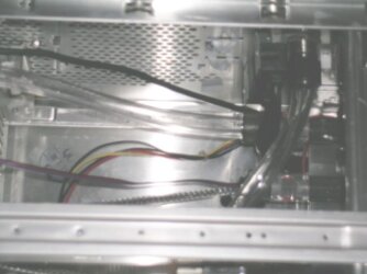
Did I mention that the system will use two interconnected loops for circulation and drainage? Well, it will, and it was a pain in the toosh to calculate the flow-rates and associated heat dissipation values. With the pumps and the fans in the system running at top speed, the system will be able to exhaust up to 748 watts of heat each minute.
Anubis_08%20-%20Side.jpg


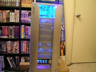
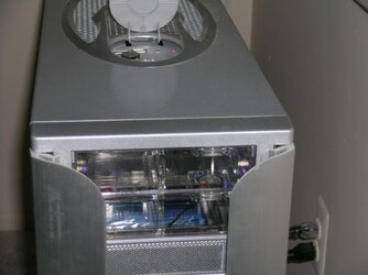
Here's a picture of the front of the case, with the bonnet opened. All of the electrical connections inside the bonnet have been preserved and more importantly still work. The stacked reservoirs are gorgeous. Although, I anticipate that bleeding air from them is going to be a pain in the toosh.
Anubis_09%20-%20Front.jpg
 
Last edited:
A few more updates

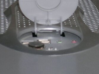
This is a close up of the bonnet. Firewire, dual USB, and audio jacks are still intact. I won't take credit for installing the fillport inside the bonnet - someone else at Xtremesystems did it first. That said, this is the first time that a fillport has been installed inside the Armor's bonnet and the original connections are still functional. ^_^
Anubis_10%20-%20Front.jpg


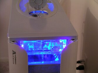
Action shot: The CCFL's blue lights are turned on.
Anubis_11%20-%20Front.jpg


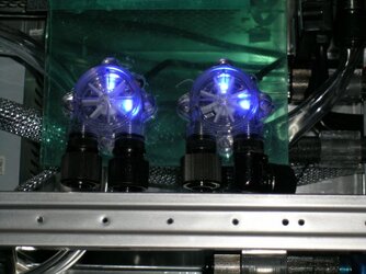
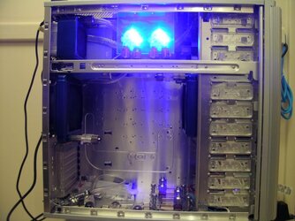
The flow meters have been mounted into a polycarbonate ("Lexan") sheet, and the sheet has been hung from the top of the case. With the ( blinding.. o_O;; ) case lights lit, this creates the visual effect that the flow meters float in mid-air, seemingly without support. The remaining fan cable has been sleeved, as well. It's hidden behind the flow meters.
Anubis_17%20-%20Side.jpg


Flow meters, without said blinding lights.
Anubis_13%20-%20Side.jpg


This is a close up of the flow meters. The fittings on the leftmost flow meter will eventually change to match that of the one on the right side.
Anubis_14%20-%20Side.jpg


(Spoken in a Mad Dr. Frankenstein voice) It's alive!!
Anubis_15%20-%20Side.jpg


Remember how I wrote that they were blinding? This is essentially the same brightness that the human eye is subjected to by the flow meters. Fortunately, once we have fluid running through them, and they're pulsing on and off in sync with the flow rate, they'll effectively be at a much lower brightness due to the PWM effect.
Anubis_16%20-%20Side.jpg


Using the camera's flash has reduced the blinding effect. Please note, the blue CCFLs are lit in this picture as well.
The two CPU blocks and the automatically-sealing drainport are at the bottom of the case.
Anubis_12%20-%20Side.jpg


I've installed DIY Fluid thermal sensors into the loop. They're difficult to see because they're made from clear acrylic parts.
Please see the post below for instructions on how to build one of your own.
Anubis_18%20-%20Side.jpg
 
Last edited:
Even more updates

A shipment from Danger Den arrived today, which included two pumps, two GPU waterblocks, and a fistful of 5 volt UV LEDs. Radiical pump tops were also received.
Both pumps have been bolted down to the floor of the case with nuts & bolts courtesy of The Home Depot. The two Radiical DDC-3.2 Turbo Mark 3 pump tops were also installed.
The pump tops have clearly been cast (apologies for the pun) and are optically transparent such that they're difficult to see in normal lighting.
This picture also shows how much the tubing kinks - even when it's run in perfectly straight lines. Fortunately, the tubing is sacrificial and will eventually be replaced.
Anubis_20%20-%20Side.jpg


Here's an action shot with the entire case lit.
Anubis_21%20-%20Side.jpg


... and the ambient light turned off.
Anubis_22%20-%20Side.jpg


More components arrived in the mail today. There were more Koolance right angle fittings, and a 2-slot SLi fitting which is used to connect the acrylic T-connector and the lower GPU waterblock. The fill line has now been routed to its final destination - it empties into the GPU pump's inlet, look just past the left flow meter.
The waterblocks have been placed close to where they will finally reside within the case.
A lot of work still needs to be completed: tubing needs measurement, cutting, & installation, and a bit of wire management needs to be performed, as well.
Anubis_23%20-%20Side.jpg


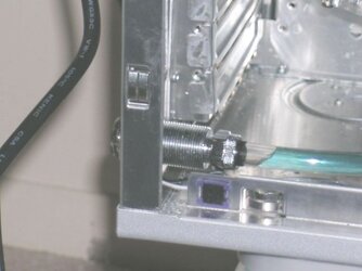
A 17mm serrated lockwasher from Grainger was received today. It was needed as a spacer between the lock nut and the automatically-sealing drainport's face.
Leak testing was also done today. I'm pleased to report that the leaks are working perfectly! Ugh.
Anubis_24%20-%20Side.jpg


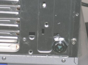
Here's the view of the drainport on the back of the case.
Anubis_25%20-%20Back.jpg


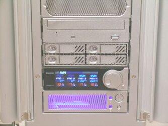
A DVD-DL Burner and 4-drive SAS Hot-swap bay have been installed. The Hot-swap bay accepts 2.5 inch SAS/SATA drives.
The lower steel pegs have been removed from the Armor's wings. The DVD-DL drive was unable to push past the Armor's magnetically held-in-place wings when they were installed.
Anubis_26%20-%20Front.jpg

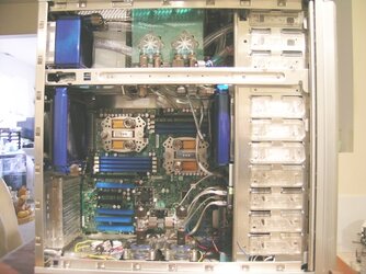
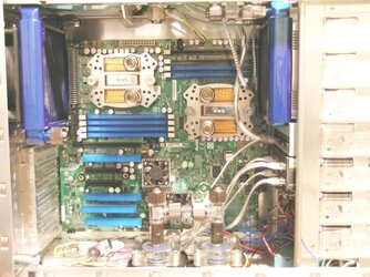
Most of the sacrificial tubing has been removed to make room for the installation of the motherboard. The two Koolance waterblocks have been dry-fitted onto the motherboard. Inexpensive UV-reactive slot protectors have been installed on most of the RAM slots and over all of the PCIe x16 slots. The SAS and SATA cables have been connected to motherboard - please look towards the bottom right of the image.
Seeing how the bottom of the case looks like a plate of spaghetti reminds us that wire management needs to be done again.
Not visible in the picture are a set of clear acrylic case feet with visible blue LEDs. A four-channel 12VDC remote will be installed to control all of the lights in the case. E.G.:
Channel 1 will be the visible blue light CCFLs. Channel 2 will be the UV light CCFLs
Channel 3 will be the four UV LEDs in the reservoir and the four UV LEDs in the pump tops. Channel 4 will be the visible blue LEDs in the case feet
Anubis_27%20-%20Side.jpg


This is a close up shot of the motherboard.
Anubis_28%20-%20Side.jpg
 
Last edited:
looks very very nice. The only issue i have with the setup is the triple radiator setups. Im sure you have reasons for this, most likely not wanting to place the radiator externally, but the three rads and dual flow meters are going to add a lot of resistance in the water setup. Couple that with the dual cpu block and gpu blocks and you have a restrictive system. Don't get me wrong, it will work, but there is potential for gains in performance. Use at least 1/2 piping if thats all going to be in one loop ( I would suggest two pumps in this case too). GL with it. What Processors are you thinking of using, and are you going to overclock the tits off'em to get all the horsepower potential you can? I sure hope so.

:welcome: to the forums btw. you'll find it a most helpful resource
 
Flow meter = Flow killer, a price to pay for looking neat

And some pumps have an RPM cable (swiftech 665) btw I think one tripple rad is enough...
edit: nvm I thought you had two 360 rads.
 
Last edited:
a) Did I miss which blocks you're to use?
b) Tygon all the way
c) PC P&C builds quality
d) Yay for engineers; we're the best
e) Welcome to the forums! :D

BTW--your wife plays Quake? Rock on!
 
Thanks to everyone for the warm welcome. ^_^

Aphex_Tom_9:
Lina thanks you. =^_~=
Air intake is through the oversized grill in the top and the two topmost drive bays in the front of the case. Outputs are at the front and rear of the case. Yes, I'm entirely aware that it's backwards as to what thermal design dictates; I.E. hot exhaust should come out of the top so as not be recirculated back inside. The computer will be in a portion of a room that receives a lot of air circulation from ventilation.

Hipcrostino:
Thanks. ^_^ Based on calculations, i.e. considering the amount of heat that can be transferred into the fluid & how quickly the radiators' fans can exhaust it; flow rates of greater than 9.08 liters per minute (2.4 GPM for US folks) won't result in any measurable ability to exhaust more heat.
I'll be using two Laing DDC-3.2 pumps at full voltage to move fluid about. With Acrylic tops from Radiical installed, those pumps are rated at ~15 liters per minute based on zero flow resistance. It won't be a problem if the flow-rate gets cut down by 30%-40% - So we'll be OK when it is. ^_^
Yes, we're going to use 13mm inner diameter tubing. 10mm would have reduced flow rates below the magic 9.08 liter/minute point.
By the way, I'm a fan of AUS Engineering. Hence the Radiical tops. ^_^

ben333:
I imagine that you'd be pleasantly surprised by how little resistance those flow meters add. I specifically need to monitor flow rate in the two loops, which the DDC-3.2 pump RPM outputs can't generate. The actual fluid flow rates will be displayed on the Zalman fan controller on the front of the case.

Anubis_386:
Thanks! ... and our apologies for stealing your name. ~_^
You really don't want to know how much metal has been removed from this Armor case to get all the kit to cleanly fit inside..

Axle:
Please try not to cringe:
Two Koolance 1/2" I.D. CPU-300-V13 waterblocks. They're no longer commerically available because they didn't create enough of an impingement effect to cool highly overclocked processors.
Mind you, there's a reason for using an inferior waterblock. We don't plan on overclocking the processors - we need the system to be as reliable as possible since it'll be used for business. The GPUs are an entirely different matter. Those are going to be overclocked and overvolted like mad. ^_^ Also, it's highly likely that the CFD (computational fluid dynamics) software that my wife uses will be ported to run on nVidia GPUs in the near future, since those types of processors are more suited to handle the massively parallel calculations than general purpose processors are.
In order of greatest importance first, the design's parameters are: system stability, reduced noise output, computational speed, and cosmetic appearance.
 
Last edited:
Usually I'm in the "against those types of flow meter's" and the "against LEDs everywhere" camp but those two flow meters are pretty sweet :D.
 
DIY Fluid Temperature sensor (clear acrylic, G 1/4 threads)

Words of warning: If you build a fluid temperature sensor in this fashion, they are not tested for high pressure, nor is there any guarantee that your favorite mixture of watercooling fluid & additives won't dissolve the adhesive sealing or the plastic protecting the thermistor itself. The pump that your aunt Bertha yanked out of her car and gave to you for Christmas might cause the thermistor to oscillate and snap off in the water flow, leading to pump seizure and meltdown. Build at your own risk!

That said, start with the following components:

Anubis_fluid_thermistor_01.jpg Bitspower G 1/4 acrylic ("crystal") plugs

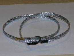
Anubis_fluid_thermistor_06.jpg Cooler Master Thermal Sensor Cable

I purchased both of these from FrozenCPU.com in the U.S. They have international shipping last I looked.

I spent an extra U.S. $4.00 to have the Sensor Cables sleeved with non-conductive "silver" mylar.
A note about FrozenCPU's sleeving: The sleeving was not long enough to cover the entire length of the sensor - about 4 inches (10.1 cm) of black wiring was left visible.

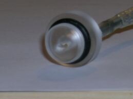
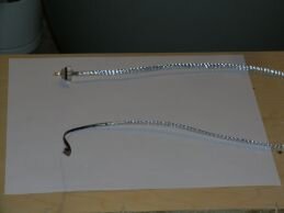
Drill a hole in the end of the G 1/4 plug. Try to make the exit hole a tiny bit larger than the orange plastic jacket.
Anubis_fluid_thermistor_05.jpg

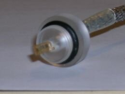
Place the thermistor through the opening
Anubis_fluid_thermistor_04.jpg


Fill the gap between the thermistor jacket and the plug with syringe-injected binary ("two part") epoxy. Also connect the top of the plug and the heatshrink tube with the epoxy. If your epoxy dispenser creates large beads of adhesive, try dispensing onto a piece of paper and use a toothpick to apply a smaller amount to the parts. Finally, coat the lower portion of the thermistor jacket with Crazy Glue to lend rigidity.
Please note: Be careful not to cover the thermistor itself with the glue. That will interfere with how quickly temperature changes are detected.
My wife asks, "Which part is the thermistor?" The thermistor is the small black dot near the tip of the orange jacket.
Anubis_fluid_thermistor_07.jpg


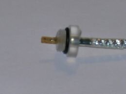
Here's a side view of the thermal sensor, the epoxy is 90% cured.
Anubis_fluid_thermistor_08.jpg


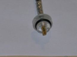
This is the finished thermal sensor.
Anubis_fluid_thermistor_09.jpg


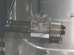
They match well with the acrylic T-connector.
Anubis_fluid_thermistor_10.jpg


IMAGE to do: Thermistor protector
Alternately, protect the thermistor with a thin metal cap. Fill the inside of the cap with your favorite brand of heat-transfer goop.
Please note: Temperature changes will not be detected as quickly because of the amount of material between the fluid and the thermistor.


Finish by installing in your water loop. Always leak test for at least 24 continuous hours before using with a live system.
Anubis_18%20-%20Side.jpg
 
Last edited:
Updated Sunday January 6, 2008

Please see the new image in the main thread, as well as the final pictures of the DIY thermal sensors.

-- Paltiel
 
Updated Wednesday January 9, 2008

Please see the new images in the main thread, as well as the the updated component list in the initial post.
 
Mini-update today. The fittings arrived, and we're taking steps to perform the initial leak test.
 
Back