• Welcome to Overclockers Forums! Join us to reply in threads, receive reduced ads, and to customize your site experience!

FT232RL-BASICSSOP

Overclockers is supported by our readers. When you click a link to make a purchase, we may earn a commission. Learn More.

cold.nut

Member
Joined
Sep 13, 2009
Location
Utah
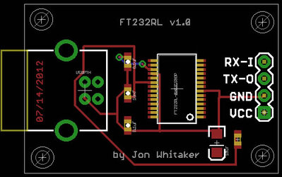
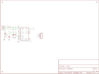
been working on some fun little circuit design on my free time. haven't had any time to bench :(. but I am running into and issue in Eagle ECAD. pin TX & RX don't have any traces coming from the 4-pin connector. GND does, but VCC, TX, & RX don't (they are Input & Output :bang head)

anyone catch the problem :shrug:
data sheet here for micro-controller.
 

Attachments

  • FT232RL v1.0 board.jpg
    FT232RL v1.0 board.jpg
    49.3 KB · Views: 540
  • FT232RL v1.0 sche.jpg
    FT232RL v1.0 sche.jpg
    184.3 KB · Views: 299
In the schematic you have a wire running across the pins, I've had that cause all sorts of interesting issues in Eagle.
That's what I'd start with. Then you can move the parts and see if the connections are attached in the schematic or not. If they get left behind in a move they aren't attached, if they get dragged along with the part they are attached.

Tips on general PCB design:
Angles sharper than 45 degrees don't etch well, ground VCC planes are your friend. As are thick traces.
If you plan on having the USB power whatever this thing is plugged into, those traces need to be bigger. 0.01" isn't capable of dealing with much current.

I love PCB design, it's fun :D

EDIT:
Found it. When you hit the auto-route button change the grid size from 50 to 5. The pins on the FTDI chip are too close together for a 50 mil grid to connect to them.
Even 10mil is too big.

2.EDIT:
FTDIboard.png
You'll have to excuse the bits that look like they're touching the upper GND plane. They aren't really, it's an artifact from screenshotting zoomed out.
At that point it's time to find a fab that can, and will, do 5mil routing.
 
Last edited:
thanks Ed :thup:! I will fix the auto-route issue when I get home. also, is there a way to set a minimum angle for auto-tracing. Eagle really likes to make those 90 degree angles. being new to Eagle and ECAD design in general, could you give me some links or more info on VCC & GND planes? :shrug: I'd like to learn how to do that.
 
The angles should clean themselves up on the finer grid.
You can destroy the wire and route it manually too of course.

The planes you make with the draw polygon tool (rectangle with a chunk bitten out). Draw the plane you want and then use the Name tool to match the name to your ground plane.
The auto-router should do the rest.
 
Back