• Welcome to Overclockers Forums! Join us to reply in threads, receive reduced ads, and to customize your site experience!

Build your own printer cable LCD Display

Overclockers is supported by our readers. When you click a link to make a purchase, we may earn a commission. Learn More.
Hey all,
I just performed this mod and it works brilliantly! :D

However:
The guide Philip posted doesn't cater for BACKLIT LCDs.
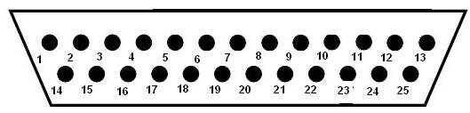
Please be aware that if you buy a backlit LCD, like white and blue etc, there will be an additional 2 pins on the LCD, 15 and 16.

These pins, 15 and 16, should be connected to the 5v line and the ground line of a molex repectively and are ABSOLUTELY NECESSARY if you want your backlit LCD to light up and operate correctly. The LCD cannot draw enough current from PIN 2 alone to light the LCD. (I simply connected pin 2 and pin 15 on the LCD to the same 5v line).

Another thing not included in the original guide is that the pin 3 on the LCD has to be connected to the ground if the LCD is to work (So i found anyway).

Hope this helps any confused parties out there...
;)
 
Here's mine. I got this unit out of an old, unused electronic dictrionary, and the smartass that I am, I tried to take it apart, and the glass fell down and cracked so no half of the top row doesn't work, but its still good for using as a spectrum analyser.
 
Does anyone have a pinout/guide for USB? This is a nice guide.. I like it, but Parallel is old and dirty lol . I rather have it as USB. I was thinking about getting one of those Parallel to USB cables, but theyre the other kind of plug, the end that goes into the printer. Would this have the same pinout as the other end of an LPT cable? Or do they change it around.. like a network crossover cable kinda deal.
 
Well, here's an addition to the sticky. For those of you that just rather chop off the female end of the LPT cable and solder the wires from the cable directly on.. I did the pinout for a cable I had. I'm not sure if different colours go to different pins on different cables.. or if the came colours go to the same pins on all cables. But here it what I got:
pin 1 - black w/ white stripe
pin 2 - short brown w/ white stripe
pin 3 - red w/ white stripe
pin 4 - red with w/ black stripe
pin 5 - orange w/ white stripe
pin 6 - short orange w/ black stripe
pin 7 - yellow w/ black stripe
pin 8 - baby blue
pin 9 - green w/ white stripe
pin 10 - green w/ black stripe
pin 11 - dark blue w/ white stripe
pin 12 - purple w/ white stripe
pin 13 - grey w/ black stripe

pin 14 - black
pin 15 - brown
pin 16 - red
pin 17 - orange
pin 18 - yellow
pin 19 - green
pin 20 - blue
pin 21 - purple
pin 22 - grey
pin 23 - white
pin 24 - pink
pin 25 - pink w/ black stripe

These pin numbers are relative to the numbers on the picture.
 

Attachments

  • lcd_wiremap.jpg
    lcd_wiremap.jpg
    12.6 KB · Views: 1,142
i have an 17in lcd how can i do this but use it in the window(take the covering and light out of it) and mount it to the window and be see through and just have it display temps and some other stuff is this possible?
 
Cyrix_2k said:
Nope... Mine died a few days ago due to my dog thinking it was a chew toy. No bite marks though, guess he felt the 1500+ volts the EL inverter dishes out...
lol i got shocked the sh** out of me touchin the back of a small one :bang head , and my finger smelt like fried skin lol
 
i have a 9in lcd tv that hooks up by s-video, but is there some software that will let it do the same thing u guys are doing? Just let it display temps and like an media player visilazation all the time?
 
this is an OLD mod...i have a few of these displays lying arround but they are cheap.
just to add to this even in know its an old thread

http://www.shopeio.com/ is the better place
http://store.earthlcd.com/ has some different displays that show up still a good place

there are some clone chips that workd the same as a hd44780 chip so keep an eye out
 
Back