• Welcome to Overclockers Forums! Join us to reply in threads, receive reduced ads, and to customize your site experience!

who here volt mods?

Overclockers is supported by our readers. When you click a link to make a purchase, we may earn a commission. Learn More.
for vdd if you think that is the problem, and you are getting TEMPFILE errors during prime, select 1.4volts in bios. this is a bug which allows 1.8 volts :)

i did it. got me 2 more fsb.
 
scooter787b said:
so i should or shouldnt do the vtt=vref from the dimm ?

IMHO no. to many dead boards. and if you use a Vr, its totally up to you what your VTT is.
 
Jess1313 said:
IMHO no. to many dead boards. and if you use a Vr, its totally up to you what your VTT is.


:-/ well im new to this, so what exactly should i do? linkys would help aswell as good explanations
 
read my post above(#18) ill try my best to get you some more pics/ links in just a sec:) heres one, please ignore everythink exept what is writen in red, it very good to know this, no one every told me......
 

Attachments

  • tictac vtt mod2.jpg
    tictac vtt mod2.jpg
    72.2 KB · Views: 1,894
Pics of Boards

Modded/cut trace.....

Abit%20NF7%20v2.0%20series%20VBT%20mod.JPG


be carefull. you must gentally cut the trace w/ a rasor(or similar) and gentaly scrape the coating off the traces so you can soder to them....

all done..... i would suggest running the wires and VR to the other side of the board, this was done only for testing befor the mod was acually figured out:)

expanded_small.jpg


and a close up......

closeup_small.jpg


and another

Abit%20NF7%20v2.0%20series%20VBT%20mod%20done.JPG

heres the Vtt mosfet......
 

Attachments

  • vtt_points.jpg
    vtt_points.jpg
    53.9 KB · Views: 1,160
Last edited:
You can also read the vtt voltage off that mosfet. The pins that read 1.54 and are circled in blue in the pic are vtt checkpoints.

I recommend, with any of these checkpoints, to solder a wire to it. Run that wire to a molex connector dedicated to voltage readings. That way you won't accidentally slip with the multimeter and short something out on the mobo.

*Edit*
I just noticed the last pic in Jess's post there are white lines pointing to the vtt measuring points on the vtt mosfet. So my pic is redundant.
 

Attachments

  • modmeassure.jpg
    modmeassure.jpg
    48.8 KB · Views: 1,093
Last edited:
thanks a bunc, so i need to scrape off some the pcb color on the traces? for the vtt? also do i need extra cooling for the vdimm mod? and vdd booster? i got a vantec iceberq on the way for nb
 
Yeah, you need to scrape it down to the metal. Otherwise your wires won't make electrical contact. ;)

For cooling, refer to the link I posted in post #5. Sink that vdimm mosfet. You'll want to sink your southbridge too. Use one of the small heatsinks that comes with the Vantec fan. Also, use Arctic Silver on the northbridge HSF.
 
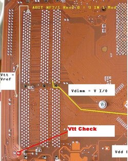
:(, i got no as5 yet, but the vantec kit is the one thats copper and comes iwht a sb,nb, and vga hsf, gonna use the vga one on nb, guess i need to order some as5 and some sinks, b4 i get started, got lots of wire from old psus guess i need several 1k resistors too?
 
yes you need 2 1k VR's. one for the Vdimm, and one for the Vtt. also it doesnt hurt to sink the Vdimm mosfet. the reason that i suggested the Vtt read point on the back of the mobo, is because the mosfet needs to be sinked, so the w/ the sink on top on it, it is rather inpossible to get a multimeter to.:p also it is hard to soder a wire to it, and still put a heat sink on it. so i would sugest runing a wire from the Vtt read point on the back to a dedicated molex conecter to measure voltage, as zachm said.

i really wouldnt do the VDD booster....
 
i would do a 5k(but w/ 5k may sure to set bios to 1.5vdd befor Vmod, becaue 1.5VDD bios w/ 5k pot =1.7Vdd acual. the 10k makes it to sensative.......
 
I've got a question about measuring vdimm. I know you can measure vdimm from the mosfet on the front of the board. I want to put a heatsink on that mosfet though. So soldering a wire to the mosfet leg to measure vdimm would interfere with the heatsink. I know you can measure vdimm from pin 7 on the dimm socket. Does anyone know where I could solder a wire to the back side of the board to measure vdimm? Here is an example of where I think might be the vdimm measure points (edit: pic is no more). I'm confused on which #7 I should solder to because there are 4 rows of pins.
 
Last edited:
you should be able to read vdimm as shown here......

EDIT: ignore Vdimm read points on this pic they are wrong, i edit the pic and reposted it below.....
 

Attachments

  • vdimm-vtt-vdd.jpg
    vdimm-vtt-vdd.jpg
    54.6 KB · Views: 278
Last edited:
Back