• Welcome to Overclockers Forums! Join us to reply in threads, receive reduced ads, and to customize your site experience!

fan controler

Overclockers is supported by our readers. When you click a link to make a purchase, we may earn a commission. Learn More.

prankstar008

Member
Joined
Jul 5, 2003
Location
San Diego, CA
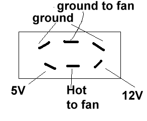
how would i go about making an fan controler with switches that look like this


| 12 V
| off
| 5V

can i have a link or directions w/o scamatix (schematics)
I CAN solder pretty well and would like this to be low budget ($10) and control 4 fans. I also want LED's lit up when the fan is on...thanks

EDIT: BTW i tried google
 
I didnt read the whole thing, but the first thing i saw was
555PWM-total.jpg


and i said no schmatics...if further along in the article there were better instructions i will feel terrible and stand corrected...ill go read the whole thing right now..
 
what so hard about schematics, do a little google search, and it'll take you three seconds to learn how to use them.
 
if all you want is a switch that will run the fan on 5v or 12v you could do what i did and buy a single pole double throw(i think thats what they are called) toggle switch. then you conect the hot wire to the fan to the middle plug and then the 5v line and 12v line from your psu to the left and right side of the middle pole. then just conect the fan ground to the ground on the psu.

it looks kinda like this


12v-hot wire to fan-5v
unused-unused-unused

if that makes any sense
 
Brad84cnc said:
if all you want is a switch that will run the fan on 5v or 12v you could do what i did and buy a single pole double throw(i think thats what they are called) toggle switch. then you conect the hot wire to the fan to the middle plug and then the 5v line and 12v line from your psu to the left and right side of the middle pole. then just conect the fan ground to the ground on the psu.

it looks kinda like this


12v-hot wire to fan-5v
unused-unused-unused

if that makes any sense

I think i get what you are saying...could you make a diagram in paint...that would eliminate the need for sooo much hardware and work because i dont want variable voltage...

BTW I know what you are saying has to do w/ this
http://www.radiativenz.com/guides/fanvoltmod/index.shtml
but Im not smart enough to figure out how to wire that to a throw switch...thanks a lot
 
here is a picture of mine
the middle wire came undone when i pulled it out if you are wondering where it is

Edit: the yellow wire is the 12v line, the red is the 5v, and the middle plug would be the hot(red) wire for the fan
 
Last edited:
And you can use the now unused legs of the switch for leds to indicate what power the fan is running at... Either two led's or a bi-color one..
 
[ADVERTISEMENT]And there's a sticky guide about making controllers...[/ADVERTISEMENT]
I plan to update it today, so you could make really simple controller. One in guide is very simple, but doesn't guarantee linear control and is dependant on power of fans used. Expect stable version with kickstart utilizing 2 cheapo transistors today. It will also have calibration to choose minimum operating voltage and I promise it will be extremely simple.

Controller of which circuit scheme is posted here (you will also find links in guide), is PWM controller. It should work, but has a few flaws. If you want minimum operating voltage of around 5v, PWM controller can be VERY simple.

Today I plan to release circuit for "simple kickstart controller", one simple PWM, one 0-12v PWM, and perhaps I'l make some progress in my "ultimate controller" project. I thought I had ready to use circuit, but there was major flaw. If I succeed, expect controller scheme cheapo and easy to make, with possibilities far beyond any controller you can buy.
 
Back