• Welcome to Overclockers Forums! Join us to reply in threads, receive reduced ads, and to customize your site experience!

Stacker Front Panel Wiring

Overclockers is supported by our readers. When you click a link to make a purchase, we may earn a commission. Learn More.

whitebloodcell

Member
Joined
Mar 30, 2005
Location
Wells, England
I picked up my Stacker 2nd on a forum at a really cheap price, since they guy decided to go at the front panel wiring, he assured me I could fix it, looking at it I have no idea what to do. So here are some farely high res picts, due to the light some things don't look great, but I'll describe them so its a bit clearer.

Firstly, The back of the panel itself.
my.php


Secondly
http://img159.imageshack.us/my.php?image=wiringcleanend9tx.jpg

The end of the wires that have ends fitted.
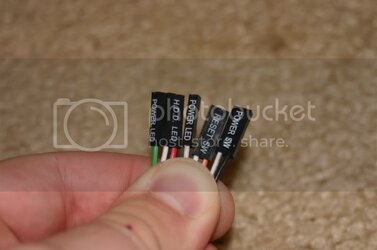
On the green and white wired plugs (2, 1 green, 1 white) there is written POWER LED
On the Black and White (One plug) is written POWER SW
On the Red and White (One Plug) HDD LED
On the Orange and White (One Plug) RESET LW

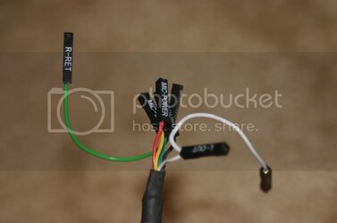
And then the hacked up wires
http://img156.imageshack.us/my.php?image=wiringloose9qz.jpg
The Red Wire (from HDD LED) leads to a Black and White one, he has soldered the black and white onto the end (poorly I might add)
The White (from the HDD LED) had also had some Black and White soldered on.
POWER LED and POWER SW have all just been pulled aprt into Single Strand Wires, though not tampered with other than Glued together lower down
RESET LW Orange and White lead to the 8pinned plug

How do I fix this?
 
whitebloodcell said:
I picked up my Stacker 2nd on a forum at a really cheap price, since they guy decided to go at the front panel wiring, he assured me I could fix it, looking at it I have no idea what to do. So here are some farely high res picts, due to the light some things don't look great, but I'll describe them so its a bit clearer.

Firstly, The back of the panel itself.
my.php


Secondly
http://img159.imageshack.us/my.php?image=wiringcleanend9tx.jpg

The end of the wires that have ends fitted.
On the green and white wired plugs (2, 1 green, 1 white) there is written POWER LED
On the Black and White (One plug) is written POWER SW
On the Red and White (One Plug) HDD LED
On the Orange and White (One Plug) RESET LW

And then the hacked up wires
http://img156.imageshack.us/my.php?image=wiringloose9qz.jpg
The Red Wire (from HDD LED) leads to a Black and White one, he has soldered the black and white onto the end (poorly I might add)
The White (from the HDD LED) had also had some Black and White soldered on.
POWER LED and POWER SW have all just been pulled aprt into Single Strand Wires, though not tampered with other than Glued together lower down
RESET LW Orange and White lead to the 8pinned plug

How do I fix this?

For the POWER SW and RESET SW leads, there should be two wires. Solder one wire from each lead to two different posts of the switch, doesn't matter which.

Then take the HD LED lead, solder each end to either end of the HD LED points on the board, and then the same goes for the POWER LED. When you put on the LED leads to the motherboard, if the LED doesn't work, try rotating the connector 180° and then plugging it back in, changing the polarity.

WOOPS, on the Power LED plug, when you plug em in, find the pinout on your mobo (should be in manual) and plug in each plug according to the pin out. if It doesn't work, then try switching the two plugs
 
If you can wait till later this evening, I can take a picture of the back of my panel all wired up from the factory.

If I understand your post, you need to know where the wires are supposed to go on the panel, right?
 
laynlow said:
If you can wait till later this evening, I can take a picture of the back of my panel all wired up from the factory.

If I understand your post, you need to know where the wires are supposed to go on the panel, right?

I can wait, thanks. Thats what I need. Though Solidsnakes post was detailed enough, thanks aswell. This is my first build so Im not sure, but should the case have come with connectors for USB and Firewire ports?
 
Yes, you should have a front panel that inserts into one of the bays. It has six usb ports, one firewire, one audio, one mic, power and reset. The usb ports are run in pairs so you have one wire coming off the panel for every two ports. 3 usb wires total. One for firewire, power switch, reset, and one each for the audio and mic.

I will get you some pictures in an hour or so.
 
laynlow said:
Yes, you should have a front panel that inserts into one of the bays. It has six usb ports, one firewire, one audio, one mic, power and reset. The usb ports are run in pairs so you have one wire coming off the panel for every two ports. 3 usb wires total. One for firewire, power switch, reset, and one each for the audio and mic.

I will get you some pictures in an hour or so.


If you didn't get everything listed, I think you just got partially scammed again.
 
SolidxSnake said:
If you didn't get everything listed, I think you just got partially scammed again.

On the contrary I think I got a good deal, I knew what I was getting, the case itself is immaculate, and it was cheap. The wiring can be fixed. He threw in 4fans and a load of other extras, UV Rounded cables, screws, fan grills x 4 (normally would cost me £4 each) etc. And an additional 4 in 3 Module. I just found the USB Cables etc. He did forget the rear fan at first but he sent it the next day. I ran out of screws so he sent me a load more, free. And the Window Side Panel. All this £50 when normally it'd cost about £150 in total.
 
Pics as promised

Ok, here we go...

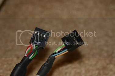
This is what the USB and Fire Wire headers look like that plug into the MB.

USBandFWheader.jpg

These are the power, leds, and reset headers that plug into the MB.

SwitchandLED.jpg

Audio and Mic connections for MB.

AudioConnections.jpg

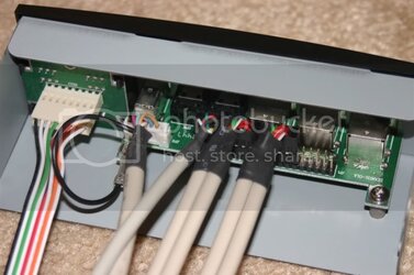
Back of panel wired up. I have removed a USB header here so you can see the size of the block. From right to left you have: USB, USB, USB, Audio, FireWire, Switches and LED's.

CircuitBoard1.jpg


EDITED TO CHANGE ORDER OF BOARD. AUDIO CONNECTION IS AFTER USB AND FIREWIRE IS THE WHITE HEADER ON THE PANEL.
 
Last edited:
e-mail [email protected] and see how much the whole panel would be to replace. That way, all the wiring would be factory attached. They were VERY quick to replace my 4-in-3 module, and sent me an additional 3.5" "open" panel for a fanbus.
 
Back