• Welcome to Overclockers Forums! Join us to reply in threads, receive reduced ads, and to customize your site experience!

The Ultimate Pentium-m Pinmod/Voltmod Guide

Overclockers is supported by our readers. When you click a link to make a purchase, we may earn a commission. Learn More.

ozzlo

Senior whose title will pier
Joined
Mar 17, 2002
Welcom to the throughly detailed Pentium-m 400 to 533mhz pinmod guide.

This is a very advanced guide which some people have felt slightly overwhelmed... If you are just looking for the basics, or something quick and ez check out this guide here...
http://www.ocforums.com/showthread.php?t=432270

Anything and everything you ever wanted to know about pin/voltmodding your pentium-m processor can be found right here... If you do decide to follow this guide and attempt a mod, You should read the entire guide not just the how to do it part.


If you have any questions or comments or sugguestions you can PM me as I usually check my messages about 3-4 times a week unless I’m on vacation (or it’s finals week).

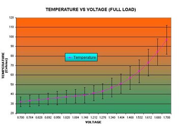
Disclaimer: This is just a guide, By following any procedures in this guide like any other time you overclock you subject yourself to being at risk of frying stuff And overclocker forums nor myself shall be blamed by the result of these risks you take. And just like with any other overclocking procedure you should overclock with caution and take baby steps and monitor your temps. Also I make references to ground and logic low a lot… Whenever I say logic low, logic low IS just like ground and so I kindof use them interchangeably FYI.

TABLE OF CONTENTS
Code:
Post 1----[COLOR=yellow]The Pentium-m Pinmod quick guide. [/COLOR]
Post 2----[COLOR=yellow]Voltmodding guide.[/COLOR]
[COLOR=DimGray]------------[/COLOR][COLOR=cyan]Interactive guide available.[/COLOR]
Post 3----[COLOR=yellow]Using NHC with your Voltmod guide.[/COLOR]
[COLOR=DimGray]------------[/COLOR][COLOR=cyan]Interactive guide available.[/COLOR]
Post 4----[COLOR=yellow]Advanced modding guide.[/COLOR]
[COLOR=DimGray]------------[/COLOR][COLOR=cyan]Interactive guide available soon![/COLOR]
Post 5----[COLOR=yellow]FAQ/SPECIAL THANKS.[/COLOR]
Quick Refrence and Recources
Code:
[URL="http://www2.ijib.com:1337/phpbb/viewtopic.php?t=3"][COLOR=yellow]Best Pinmod Guide I’ve found on the internet[/COLOR][/URL]
[URL="http://www.notebookforums.com/showthread.php?t=80879"][COLOR=yellow]Pinmod guide with plenty of photos[/COLOR][/URL]
[URL="http://processorfinder.intel.com/scripts/list.asp"][COLOR=yellow]Intel sSpec chart to find the correct processor[/COLOR][/URL]
[URL="http://files.extremeoverclocking.com/file.php?f=103"][COLOR=yellow]Prime 95[/COLOR][/URL]
[URL="http://www.pbus-167.com/chc_guid.htm"][COLOR=yellow]Notebook Hardware Control (NHC)[/COLOR][/URL]
[URL="http://www.uoregon.edu/%7Ejhochspe/blackup/VOLTMOD%20INTERACTIVE%20GUIDE.xls"][COLOR=yellow][/COLOR][/URL][URL="http://www.intel.com/design/mobile/pentiumm/documentation.htm"][COLOR=yellow]INTEL Pentium-m Technical Docs[/COLOR][/URL]
THE PINMOD PROCESS


Intro: Well There are several guides out there on how to pinmod your processor in fact there’s tons of guides out there… just name an overclocking forum and they will probably have a guide… Because my focus isn’t just on the pinmod but the entire package deal I have turned my focus towards more advanced tequniques and thus this pinmod guide I have provided is very basic. The best guide I have seen can be found here http://www2.ijib.com:1337/phpbb/viewtopic.php?t=3 [ THIS LINK has either been taken down or moved... I'm working on tracking it down] but read on first to see what you may be getting yourself into.


CONCEPTS BEHIND THE PINMOD

The concept is that an ordinary 400mhz fsb Pentium-m processor can be overclocked by placing the chip in a motherboard capable of running at 533mhz (aka the i915 chipset). By grounding the correct pin on the chip, this will “trick” the motherboard into seeing the processor as a 533mhz processor when it actually is a 400mhz processor. The motherboard will then supply a 533mhz FSB for the processor instead of the normal 400mhz fsb. This causes the processor to achieve a nice 33% overclock. Sometimes after this pinmod the overclock is not fully stable so a voltmod needs to be implemented in order to make the chip fully stable. The voltmod process will be covered in grave detail in the next post.

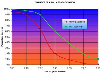
Pinmodding 1.5,1.6 and 1.7ghz processors have very high success rates but faster processors may not work. For approximate sucuess rates see the graph in post #2.

FINDING THE CORRECT PROCESSOR (NOT FOUND IN ORDINARY PINMOD GUIDES)

1. FIND THE sSPEC alphanumeric number, which is 5 digits long on your current processor it should be a code etched into the package below the core.
2. Open up this Intel spec sheet... http://processorfinder.intel.com/scripts/list.asp
3. Look down the left column of sSPEC#'s to find your processor
4. Once you found it look all the way to the right of the sheet to find out how many pins it has.
5. Decide on a speed that you want to get (remember after the pin mod it will be 33% faster) and remember you NEED A 400mhz processor (weather a bianas or dothan core, eigther will work but the dothan core is definatelly perferred because it peforms better)
6. Find the processor with the speed you want that has the same number of pins as your current processor.
7. Write down that sSPEC #
8. Shop for Pentium-m's that only have the sSPEC # that you wrote down


HOW TO PINMOD (VERY SIMPLIFIED VERSION)

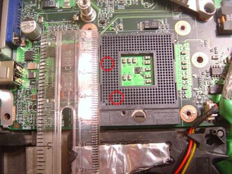
The pinmod process requires that the Bsel[0] pin be shorted to ground. Here are the steps, which will pinmod your Pentium-m.

If you’re looking for a photo guide look no further than this guide… (good pic of how big the wire should be, included ;))
http://www.notebookforums.com/showthread.php?t=80879

1. Make sure you have a 400mhz Pentium-m processor that fits your socket before you begin.
2. Take out your existing processor if it is in the socket
3. Make a 3/8” long wire preferably out of 30 or 32 gauge wire or a strand of speaker wire.
4. Insert one end of the wire into the hole on the socket labeled C16 and the other wire in the adjacent hole labeled B16 (if your having problems with locating the correct hole just think Battleship ;) and the markings are next to the socket on the motherboard)
5. Insert the processor into the socket.
6. Apply artic silver to the core, a good Guide can be found here http://www.arcticsilver.com/arctic_silver_instructions_big2.htm
7. Check to make sure the chip is running and check for stability with prime95, if the processor is not stable then you can try a voltmod (see post #2)


Note: The pics below are examples only, Do not mod vid 4 unless you are really crazy!
 

Attachments

  • vidmod table.jpg
    vidmod table.jpg
    52.8 KB · Views: 20,696
  • pinout.jpg
    pinout.jpg
    34.9 KB · Views: 24,919
  • DSC00002.jpg
    DSC00002.jpg
    122.6 KB · Views: 22,921
Last edited:
THE VOLTMOD PROCESS

A Pentium-m Voltmod greatly increases your chances of having a stable processor after pinmodding or overclocking it. The tequnique to voltmod is very similar to how you pinmod and you should always consider the possibility of having to perform a voltmod if your pinmod is not stable. Minor voltmods may only raise your temps by 3-5c while major voltmods can cause your processor to run at 90c without custom cooling… By shorting certain pins on your processor you can achieve any voltage between .7v and 1.708v but forcing the voltage lower than stock voltage can much more easily be done with software (see post #3) and thus the primary focus of this guide is to increase the processor voltage not decrease.

Here is a good Idea of what a difference in stability the voltmod can make. In this graph below you can easily see the higher pinmod sucuess rates when coupled with a voltmod.
Chances.jpg


CONCEPTS BEHIND THE VOLTMOD

There are 6 pins on your Pentium-m processor, which send signals to your motherboard requesting a specific voltage. Each pin represents a different voltage and the total voltage to be supplied to the processor is the values of all the pins added together +.7v. Each pin has 2 states, which means that certain pins may or may not request voltages depending on it’s logic state. Throughout this guide these pins will be named VID pins and each pin has a number 0-5. as I said each pin can request a specific voltage and here are the voltages that each pin can request.

Code:
vid 0 =.016v boost
vid 1 =.032v boost 
vid 2 =.064v boost
vid 3 =.128v normally requested
vid 4 =.256v boost 
vid 5 =.512v normally requested
THE EFFECTS OF SHORTING VOLTAGE REQUEST PINS TO LOGIC LOW

There are 64 different possible voltages that your processor can request with those 6 pins. Here are all the possible voltages that your processor can run at.
vidmod%20table.jpg

Image swiped from http://images.sudhian.com/articles/P-M Overclock/

As you can clearly see that the different combinations of the pins request different voltages. And if you look at the red-boxed areas, the only difference between those two voltages is that one pin is switched off (or set to logic low). Now the maximum stock voltage is 1.34v so any voltage higher than this has to be the result of a voltmod. As in the pic above the only way to get that voltage highlighted in the upper red box would to be to mod VID 4 to a logic low pin.

Now still referring to that pic above if you recall what I showed earlier
modding vid 4 =.256v boost

You can see that modding that pin in that particular situation gave us a .256v boost. We can add additional voltage if we want by modding additional pins… any pin that is still a “1” in upper red box can be set to a zero to increase the voltage further. So if we wanted to push the voltage further we can for example mod VID 1 also giving another .032v boost…. Under normal situations you would not want to put that much voltage through your processor…. This is just an example.


An Alternative explanation which may help if your stuck

This explanation uses the same table as the first explanation did ^^ look up for the table^^.

TO make sense of this very confusing mod, Look at the very bottom right hand corner of the table which says .700v

in the same row as the .700v you will see a series of 6 "1" 's which represent logic high value of 6 Vid's {WHICH REPRESENTS THE HIGH VOLTAGE STATE ON 6 CORROSPONDING "VOLTAGE REQUEST" PINS ON THE PROCESSOR}. Now look at the next row up (.716).

Notice in the .716 row that the furthest right "1" has changed to a zero. If you go to the top of the column you will see that this column (the one the 1 changed to a zero) is represented by Vid 0. In my list that I made above the table I posted I have Vid 0 listed as = .016v now if you compare the 2 rows (the .7v row and the .716 row) and you take the difference of the two rows that you will end up with a voltage difference of .016v. Well what do you know... is that a coincidence or what?


So the processor has a base voltage of .7v (that's the lowest that the voltage can go) any 1's that are changed to zero's will request more voltage from the motherboard. So If Vid 2 is set to zero then the processor will request .7v + the voltage value of vid 2 which is .064v.


Your processor normally requests 1.340v which means that it normally requests Vid 5 and Vid 3 as logic low so thus .7v base voltage + .512v +.128v = 1.340v

Now if you want to manually request more voltage than what the processor normally requests you can pin mod Vid 4, Vid 2, Vid 1, OR Vid 0 or any combination of the 4. I modded Vid 2 which set the "1" in the Vid 2 column of the table above from a "1" to a "0" which then requests an extra .064v from the motherboard on top of the 1.340v already requested by the processor.


WHAT VOLTAGE SHOULD I USE?

You should use only the minimum voltage necessary that makes you computer 100% Stable + .016v safety margin. The peferred programs of choice for stability testing is Prime 95 and Centrino Hardware Controll’s Stability tests.
http://files.extremeoverclocking.com/file.php?f=103
The best Way to find that perfect voltage is to start at stock voltage and Test to see if the processor is stable. If it is not then you can increase the voltage by a little bit by using the right combination of modded pins. Once you have found your stable voltage, you should add an additional .016v as a safety margin to compensate for voltage fluxuations.

To get a good Idea of what you can expect from voltmodding your processor you can look here to see about what voltages certain speeds will run at. Just a disclaimer that there are oddball processors that will be stable at voltages way higher and way lower than the ranges in the graph. Furthermore some processors may not work no matter how much voltage you add.
Voltage%20vs%20Speed.jpg


IS THERE AN EZ WAY TO FIGURE OUT THE PROPER PINS TO MOD?

Why YES there is. I have made an interactive VOLTMODDING GUIDE. You tell the guide which voltage you want and the guide will tell you which pins to mod and show you a diagram of the socket with the locations of the pins and Red bars representing the correct pins to mod to get the voltage you want. I apologize but the Interactive guide is in a spreadsheet form and you will need either Microsoft excel or open office to view this guide. BTW open office is free and you can get it at www.openoffice.org

See attached files to download the interactive guide
If You can’t view the guide then you can use the list below.

How to read this…
--- Example VID 1+0 means you need to short VID 0 to logic low and short VID 1 to logic low.
Code:
1.356v > VID 0
1.372v > VID 1
1.388v > VID 1+0
1.404v > VID 2
1.420v > VID 2+0
1.436v > VID 2+1
1.452v > VID 2+1+0
TO get values inbetween 1.452v and 1.596v see the advanced section (post # 4) of this guide below.
Warning! Using unusually High voltages can cause extreme heat and even damage your cpu, use the voltages below at your own risk.

Code:
1.596v > VID 4
1.612v > VID 4+0
1.628v > VID 4+1
1.644v > VID 4+1+0
1.660v > VID 4+2
1.676v > VID 4+2+0
1.692v > VID 4+2+1
1.708v > VID 4+2+1+0
THE LOCATION OF THE PINS ON YOUR PROCESSOR


pinout.jpg

Image swiped from http://images.sudhian.com/articles/P-M Overclock/

Normally you would not mod vid 4 as that requests an extreme amount of voltage. It is just an example of how you would mod a vid pin.

Here are the locations of the VID pins that I have been explaining. After you figure out which pin you need to set to logic low (use my interactive guide to figure that out), all you need to do is put a very tiny wire (less than 3/8" long) and approx 32 gauge wire or a single strand of speaker wire and short the Vid # to VSS.
 

Attachments

  • temp vs voltage.jpg
    temp vs voltage.jpg
    27.8 KB · Views: 19,503
  • Voltage vs Speed.jpg
    Voltage vs Speed.jpg
    22.6 KB · Views: 19,479
  • Chances.jpg
    Chances.jpg
    29.7 KB · Views: 19,451
  • VOLTMOD INTERACTIVE GUIDE.xls
    23.5 KB · Views: 873
  • VOLTMODTABLE.xls
    54.5 KB · Views: 712
Last edited:
USING NOTEBOOK HARDWARE CONTROL WITH YOUR PINMOD


Beginners guide to NHC can be found HERE
http://www.pbus-167.com/chc_guid.htm

Notebook Hardware Control (from here on known as NHC) is an invaluable tool to reducing temperatures and increasing battery life. This chart below approximately shows the temperatures you can expect from your processor at a given voltage. Just a disclaimer: all laptops have different levels of cooling, your laptop may have better/worse cooling and thus have better/worse temperatures. Your mileage may Vary.
temp%20vs%20voltage.jpg


As stated earlier, NHC is a great tool for reducing the voltages and saving battery power and reducing heat But when Combined with a voltmod of any kind the voltages in NHC can be incorrectly set/reported (in some cases NHC can be as much as 30% off). In order to properly use NHC you must compensate the values in NHC with your pinmod.

For Example…
You have modded VID 2 and your trying to set the minimum voltage to .828v in NHC.
Well the logic values for the voltage request pins for .828v is
(VID0)=1 (VID1)=0(VID2)=1 (VID3)=0 (VID4)=1 (VID5)=1

Notice that vid 2 is set to logic high…. BUT in this example VID 2 has been modded to logic low (in fact it is forced to logic low NO MATTER WHAT) so the VID pins are actually requesting
(VID0)=1 (VID1)=0(VID2)=0 (VID3)=0 (VID4)=1 (VID5)=1
which is the logic pinout for .892v .64v more than requested in NHC


HOW MANY VOLTAGES ARE AFFECTED?

The VID pins can be combined in any combination to create any of 64 different voltages. 41 of those 64voltages are used in NHC to lower your voltage down from stock. (the other 23 voltages cant be used because they are above stock voltage)
It is inevitable that you are going to loose some range of voltages when you pinmod.

For Example…
Modding one pin= you loose 32 voltages (only 20 left usable in NHC)
Modding two pins= you loose 32 voltages plus an additional 16 voltages = 48 voltages affected. (only 10 left usable in NHC)
Modding three pins = 32+16+8… (you only have 5 voltages that are reported correctly and set correctly in NHC)
Modding all 6 pins = you can only use 1 voltage… setting voltages to anything other than 1.708v in NHC will set the voltage to 1.708v no matter what.


So are they disabled or what?
Why aren’t they usable in NHC you ask?

If you where to select a particular voltage in NHC that was affected it would jump up to a voltage equal to the difference between max stock voltage and the max voltage of the pinmod. So it does become impossible to set the particular voltage.

So for instance if you modded VID 2 to logic low, all the voltages that normally have VID 2 set as logic high will be affected and they will jump up by .64v which is the difference between 1.404v (pinmodded max voltage) and 1.340v (stock voltage).


WHAT CAN I DO TO MINIMIZE THIS?


The first thing you can do is try not to mod more pins than you have to… each time you set a voltage request pin to logic low, you make it impossible to use certain voltages. Modding a second pin will make additional voltages impossible to use. If you want more range of voltages to choose from in NHC, you should not mod more pins than you need to. And in some cases it may be worth it to step the voltage up to the very next level to increase the range of voltages to choose from.

For Example…
Your processor is stable at 1.388v… but the voltmod required for 1.388v requires you to mod VID 0 and VID 1. by stepping up to the very next voltage level (adding .016v), you only need to mod VID 2 which will give you 50% more voltages to work with in NHC. This will allow you more flexibility when you select your voltages in NHC.


HOW CAN I FIGURE OUT WHICH VOLTAGES ARE AFFECTED?

Any voltage that would normally have a VID logic high but instead that VID is logic low because of the voltmod is affected.


Ok so this is one of the most complicated parts of this guide (except for maybe some stuff in the advanced part) so I decided instead of throwing even more words at you I would give you my INTERACTIVE NHC CALLIBRATION GUIDE right off of the bat. Like the interactive Voltmod guide, it too is a spreadsheet file, so you will need MS excel or Open Office in order to view this.

See attached files to download the NHC calibration guide

If you for some reason cant view the guide above you can use this table below. This table lists the voltages in Centrino Hardware Control which are not affected by your voltmod and are safe to use. Listed by column under the pin you modded. Also note that this table does not include 1.340v which is your max voltage which will be increased to whatever voltage you pinmodded to.
Code:
[U]VID 0[/U]-----[U]VID 1[/U]-----[U]VID 2[/U]-----[U]VID 0+1[/U]
0.716-----0.732-----0.764-----0.748
0.748-----0.748-----0.780-----0.812
0.780-----0.796-----0.796-----0.876
0.812-----0.812-----0.812-----0.940
0.844-----0.860-----0.892-----1.004
0.876-----0.876-----0.908-----1.068
0.908-----0.924-----0.924-----1.132
0.940-----0.940-----0.940-----1.196
0.972-----0.988-----1.020-----1.260
1.004-----1.004-----1.036-----1.324
1.036-----1.052-----1.052
1.068-----1.068-----1.068
1.100-----1.116-----1.148
1.132-----1.132-----1.164
1.164-----1.180-----1.180
1.196-----1.196-----1.196
1.228-----1.244-----1.276
1.260-----1.260-----1.292
1.292-----1.308-----1.308
1.324-----1.324-----1.324
ok so how did I come up with those numbers you ask? Well any voltage used where the VID of the modded pin is 1 is affected.

For Example…
If I modded VID 2 then any voltage where VID 2 is a 1 is in reality a 0 and is boosted by the value of VID 2 (.064v). So if we where to try to use 1.260v in CHC with a VID 2 voltmod, VID 2 is a 1 (logic high). So because by modding vid 2 to logic low, ALL voltages that have VID 2 as logic high are FORCED to logic low which will increase the voltage. Any voltage where VID 2 is 0 is not affected. So in the table above under the VID 2 column, those are all the voltages where VID 2 is already 0 and thus is not affected by the VID 2 voltmod. If you choose to mod 2 pins then the logic level of bolth VID pins must be 0 in order for that voltage to not be affected thus there are a lot less voltages to choose from because 2 VID’s as 0 vs 1 VID as 0 happen half as often.
 

Attachments

  • NHC Voltmod Calibration Guide.xls
    42 KB · Views: 572
Last edited:
ADVANCED STUFF


If you choose to try these things you do so knowing that you are at high risk of frying something and I take no responsibility This stuff is for people who have a very good understanding of the inner workings of the Pentium-m processor and are willing to take a much larger risk than some of the less extreme mods.

1.468v-1.580v (EXTENDED RANGE METHOD)

If you diden’t realize this… The voltage range between 1.468v and 1.580v is impossible to achieve by pinmodding alone because vid 3 is already logic low. So modding vid 3 to logic low dosen’t add any voltage. This mod involves a great deal of risk as the mod requires modding to extreme voltages and then backing the voltage off after bootup with software. This tequnique will involve modding VID 4 (the pin I’ve warned you against modding several times previously in this guide) and then cutting back the voltage with Notebook Hardware Control. This mod WILL cause extreme stress on your system during bootup and the mod it’s self is not gaurenteed to make your processor stable as some chips wont ever be stable no matter how much voltage you throw at them. the only reason you would attempt this mod is if you where a hardcore oc’er attempting a 2.4ghz or 2.66ghz pinmod anyways and is the only instance where this mod may be required(unless of course you’re a desktop overclocker ). If you are considering an extreme 2.4ghz or 2.66ghz pinmod then you should consider the possibility of having to do this mod before you begin your overclocking venture.
 

Attachments

  • REVERSE pinmod.jpg
    REVERSE pinmod.jpg
    39.6 KB · Views: 20,309
Last edited:
Q & A


Q: Can I use my 533 mhz processor to do the Pinmod?
A: No you need a 400mhz processor for it to work.

Q: Which chipset do I need?
A: You need the intel i915 mobile chipset(any of the variations will do) to pinmod.

Q: What voltage should I use ?
A: You should use the minimum voltage necessary that will also ensure 100% stability.

Q: Will this work with the 400mhz Celeron-m processor?
A: If the processor works on the i915 chipset running at 400mhz then yes you can pinmod it to 533.

Q: Has there been any situation where the pinmod or voltmod have not worked.
A: Yes I have been in contact with one poor guy who’s laptop refused to pinmod because his board has FSB setting jumpers on it and somehow it was causing complications with the pinmod. Also some processors may not overclock no matter how much voltage you add and this is just a “luck of the draw” type of thing.

Q: Can you pinmod the new 667mhz Yonah processors.
A: No, currently there is no indication that Yonah processors can be pinmodded to 800mhz. BUT according to intel schematics there are some “RESERVED” pin combinations for fsb selection which one may turn out to be what we need. BUT don’t get your hopes up that high as pinmodding from 667mhz to 800mhz is only a 17% speed increase, much less than the current 400 to 533pinmod.

Q: Can I pinmod my 533 processor with the new 667mhz chipsets?
A: No the pinouts are different and the 533mhz processor does not have the ability to set a frequency of 667mhz.

Q: Will the pinmod/voltmod work on desktop systems?
A: If you got the right chipset/socket then YES.

Q: Can I fry my chip pinmodding/voltmodding?
A: Yes there is a very small possibility (just like when overclocking any other cpu) but I’ve not seen it happen though I have seen a few failures where the chip just did not want to run that fast no matter how much voltage was added but the chip was not fried it just diden’t want to run that fast most of the time failures occour on the higher speeds 2.4ghz – 2.8ghz…

Q: If I have 400mhz ram will my ram become overclocked?
A: No the memory controller on the i915 chipset has it’s own clock generator and will only run the memory at it’s rated speed.

Q: Will voltmodding my CPU shorten my battery life?
A: Yes it can but the effect is greatest when at full load which your CPU usually isn’t at full load unless your doing something CPU intensive, using NHC to undervolt the Lower frequencies you can counter this effect and even extend your battery time…


SPECIAL THANKS


A very special thanks goes out to the dedicated members of www.laptopforums.com who pioneered some of the first Pentium-m laptop pinmods/ voltmods whom got me started in my own research upon the matter.

Another special thanks goes to Intel for having their 100+ page technical documents available to download by the public. Without those documents these mods would have been almost impossible to research ;)


Special thanks to the following Ocforums members for their contributions.

Jigpu- for lending a good ear and being a Grammar Nazi for final editing before publishing. (if there are any grammar mistakes in this guide it is solely his fault :D)

d]g[ts- for indirectly giving me the idea to use code tags to clean up the guide.

Audioaficionado & RoadWarrior for showing me good techniques for insulating pins and logic high mods which I am currently researching and will post when I finish my research.
 
OH shoot... It took me awhile to figure out what you meant as I just realized it's April 1st lol. This guide is 100% legit. I posted it today because I got the day off from work lol. I am still working on making it more readable which shoulden't take too long. I'm almost thinking I shoulda posted this tomorrow lol...
 
If I would have had something like this when I swapped out cpu's in my 9300, I would've been more inclined to use a 745 or 755 centrino.
 
i found the guide great and would have been one hell of a time saver if i had it before i pin modded and volt modded my 735
i found it gighley accurate also.
i even learned a few things i didnt know or remember.
i went back and made sure i was useing only the voltage settings in nhc that werent affected by the mod.i had 2 or 3 that were set incorrectly.that equals more power saving also.
ty for all the hard work!
 
Nice work...I'll sticky this. I think it will be very helpful to many of our members here.
:)

Matt
 
awsome, Thanks...

If anybody has any questions about this guide I am allways willing to help ;)


I have decided not to add some of the advanced mods i'm working on until I can personally verify that they work. They look good on paper but bridging two pins that are 7+ holes apart witout a pcb mod is no ez task.
 
got a question that should be added to the Q/A..

that sweet excel datasheet you made (love it, by the way)... is it showing pins in the SOCKET or the bottom of the CHIP?
i just dont want to get all turned around and fry my mobo, chip, or both...
 
that's looking at the holes on the socket... you can also kinda figure that out by which way the letters and numbers go... I will try to note that in the spreadsheet... Thanks for the feedback :)


also the very very first time I attempted the pinmod I diden't notice that the socket was rotated 90 degrees... :EEK: but nothing fried, it just diden't boot I guess I consider myself lucky but according to the intel documents the processor is somewhat able to sense shorts and such and de-activate it's self to prevent damage...
 
Thanks for the guide, did the pin mod on my z60t, (too afraid to do it on new t43p), and it worked like a charm. Went from a Celeron M @ 1.4 to 1.86, the great thing is that the ram is also running at 533 and not slowed down by the Celeron anymore. The temps went up from about 38 idle to 46 idle, any software to adjust it with and not do it manually?

1863mq.jpg
 
assuming your talking about your new t43...
unfortunatelly I have not seen a laptop with a i915 chipset have an unlocked PLL for software manipulation to date...

you can however still use NHC to get lower voltages and such but I think you allready knew that judging by the NHC icon in your taskbar...
 
Not sure what you meant with the t43 comment, but it was done on a Z60t, so NHC cant adjust volatages on the C-M, unless im missing something. And although I dont need to adjust voltage to keep it stable since Prime-95 is running for an hour w/o error, the temps are a little high and changing the coltage proably would help as you said.
 
OH I thought you where talking about overclocking the T43 with software lol don't ask me how I got that out of your post...


I knew that celeron-m's don't have speedstep but it just never occured to me (until now) that you might not be able to regulate voltages in NHC. If it's greyed out in nhc then your outta luck...

48c idle... did you do any voltmods? you might want to redo your AS5 job agan as that seems kinda on the warm side especially for only 1.86ghz... maybe the goop is too thick or maybe the heatsync isn't tightened down all the way... :shrug:


I have been working on a special kind of voltmod that will actually LOWER your voltages from normal instead of raise them... BUT I haven't found a good way of doing the mod without having a large chance of FRYING THE CPU... I'm still working on it, and I may never find a way to get it to work but if I ever do, It will be posted in the advanced section of my guide...
 
Last edited:
I think the AS5 didnt harden, and after doing the Prime 95 at around 55C the temps droped to 38C idle, pretty impressive since that only 1 degree of what it was at 1.4. For some reason the super pi scores seems a bit high for 2M, a score of 2m and 10 sec, although might have been some programs in the backround.

Thanks again for the guide, easy to do and great results, and when the warranty expires it will defently be done on the t43. :cool:
 
Back