• Welcome to Overclockers Forums! Join us to reply in threads, receive reduced ads, and to customize your site experience!

External CMOS Reset Key Switch

Overclockers is supported by our readers. When you click a link to make a purchase, we may earn a commission. Learn More.

Jolly-Swagman

Member
Joined
Sep 20, 2007
Jolly Swagman's Mods

External CMOS Reset Key Switch​

This Mod was performed on my CM-690 Case
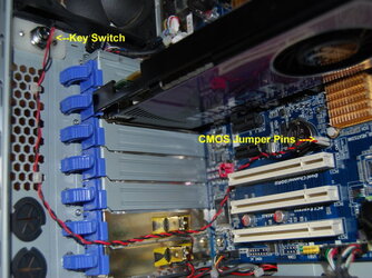
NOTE - this mod pertains to a 2 pin clear CMOS jumper on some newer motherboards and other have 3 pin reset jumper

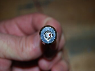
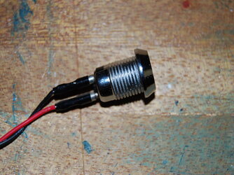
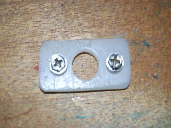
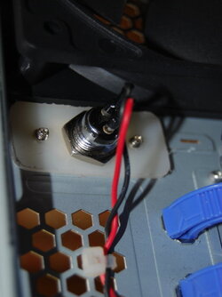
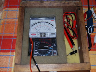
First obtain a Key switch, the one I am using for this Mod is a barrel type as shown in pic #1 # pic#2 below,

I have attached 2 wires 450mm in length soldered and shrink tubed to switch terminals and the other end has pin socket terminals to fit jumper pins.

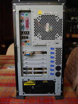
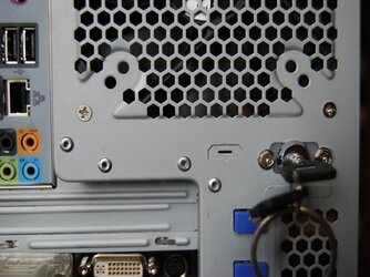
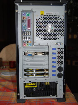
Now find a suitable position for your switch, at the back of case see pic#3.
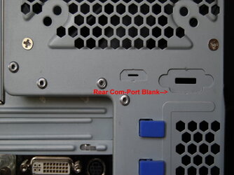
now seeing as I am going for the no drill hole in case method, I will be utilising the blank com port located just below the exhaust fan grill, see pic #4.

Now I have made a custom retainer for my switch using 3mm PVC material and drilled mounting hole for switch and mounting screws to coincide with the com port see pic #5

Now remove the Blank for com port (pic #4) and install mounting retainer to the inside of case and screw down.

Continued Post 2
 

Attachments

  • Key Switch.jpg
    Key Switch.jpg
    26 KB · Views: 3,268
  • Key Switch - 1.jpg
    Key Switch - 1.jpg
    70.8 KB · Views: 3,180
  • Rear CM-690 Case.jpg
    Rear CM-690 Case.jpg
    77.4 KB · Views: 3,194
  • Rear CM-690 Case Com-port Blank.jpg
    Rear CM-690 Case Com-port Blank.jpg
    51.7 KB · Views: 3,122
  • Plastic Retaining Plate.jpg
    Plastic Retaining Plate.jpg
    73.7 KB · Views: 3,123
Now pop wires from switch through the hole replace retaining nut on switch and tighten firmly and secure wiring. see pic #6

Now we will test the switch using your trusty multimeter before connecting to the motherboard, so as that we have the Switch in the OFF or Normally Open position. see pic #7 & pics # 8-9
( The Sanwa Multimeter that I am using I have had for the past 32 years got for my 16th birthday )

Now I have placed a RED DOT below Switch to show position when switched to Normally Closed to Clear CMOS the you would swith back to Normally Open and remove Key. See pic #10

Continued Post 3
 

Attachments

  • Key Switch Retaining Plate.jpg
    Key Switch Retaining Plate.jpg
    42.6 KB · Views: 3,105
  • Key Swich Testing.jpg
    Key Swich Testing.jpg
    67.3 KB · Views: 3,146
  • Key Swich Testing. Normal Closed CMOS.jpg
    Key Swich Testing. Normal Closed CMOS.jpg
    87.5 KB · Views: 3,080
  • Key Swich Testing. Normal Open CMOS.jpg
    Key Swich Testing. Normal Open CMOS.jpg
    90.9 KB · Views: 3,071
  • Rear CM-690 Case. Key Switch.jpg
    Rear CM-690 Case. Key Switch.jpg
    47 KB · Views: 3,082
Last edited:
Now we connect the switch leads to the the pins on the CLR CMOS jumper as indicated in pic #11 below.

And now we can put the case side on and hopefully when a need to reset the CMOS the case side wont have to be taken off just use of the CLR CMOS Key Switch as seen in pic #12 and swith to the RED DOT for a few seconds and the CMOS will be RESET.

And the finished Project Pic #13

Hope this will be Useful to you as it has for me.


Jolly SWagman
 

Attachments

  • My PC Stuff 020.jpg
    My PC Stuff 020.jpg
    89.3 KB · Views: 3,106
  • Rear CM-690 Case. Key Switch.jpg
    Rear CM-690 Case. Key Switch.jpg
    47 KB · Views: 3,008
  • Rear CM-690 Case. Key Switch.-1.jpg
    Rear CM-690 Case. Key Switch.-1.jpg
    74.4 KB · Views: 3,017
Last edited:
I'll be doing this to my first build computer as i will be OC'ing it and i'm sure i'll make many mistakes. Is there anything about this process that a Noob Oc'er should know?
 
That looks like a keyboard lock :p I might try this, I've done it inline with my power button before.
 
I'll be doing this to my first build computer as i will be OC'ing it and i'm sure i'll make many mistakes. Is there anything about this process that a Noob Oc'er should know?

Its fairly Straight forward just one Important note is to make sure you have tested the key switch to check N/O N/C positions and have the switch in the Normally OPEN state before you connect to motherboard , as you close the switch to reset the CMOS
 
i rember some one doing something similar with a Turbo Button off an old computer, the locks a good idea so som doofus doesent clear it while they are dicking arround with your computer
 
For those with 3-pin CMOS clear jumper blocks, connecting the key wires to the outer pins and grounding the middle pin to the key casing should work. And that's assuming that the third pin is even connected to anything (or if it's just a holder for the jumper when you're not clearing CMOS, in which case you could just ignore it).

BTW, nice revival, gigabit. Seven months is nothing, though... the seven YEAR revivals take serious skill :p
 
:drool: man that is a good idea i will be doing that too, wow i wish i chould think of stuff like that
 
i'm thinking about useing this .... what yall think about this switch???
push_button_leads.jpg


http://www.wiringproducts.com/index...get=d35.html&gclid=CIzQ9NuH2JYCFRLoxgodm1AFyA
 
Here is another Type of toggle switch called a latching lock-type that cannot be accidentally switched.

You have to pull switch slightly outward in order to get over the latch (up and over so to say) in order to change switch position

531556.jpg


And also can be used for 2pin or 3pin CMOS reset
 
This is a great idea, I think i might adapt it in the future for the power switch on my file server, stop people turning it off when i'm not around. Thank you for the write-up.
 
This is a great idea, I think i might adapt it in the future for the power switch on my file server, stop people turning it off when i'm not around. Thank you for the write-up.

You're Welcome j0rd, glad it was of some help to you for ideas!
 
Back