• Welcome to Overclockers Forums! Join us to reply in threads, receive reduced ads, and to customize your site experience!

Water Cooled Framer Project

Overclockers is supported by our readers. When you click a link to make a purchase, we may earn a commission. Learn More.
Me, I've got the basement of the apartment we're renting. Better than the kitchen, where I started.


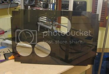
New set of holes for airflow to the motherboard:


Bottompanelfinished.jpg


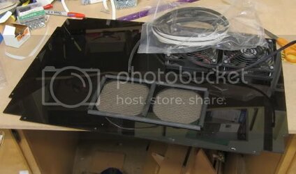
The radiator holes get some gasket sealing:


Bottompanelgasket.jpg


I should mention that the radiator and its fans are mounted to the frame itself--for obvious reasons it shouldn't be moved (as it will eventually be connected by water filled tubing to the motherboard). The panel merely has holes to let air pass thru--the panel can be easily removed without tinkering with the radiator.

The airflow fans, tho, don't weight much, and can be easily disconnected, and so they mount directly to the plastic panel.


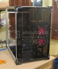
From the bottom:

Bottompanelcompletedandmounted-1.jpg


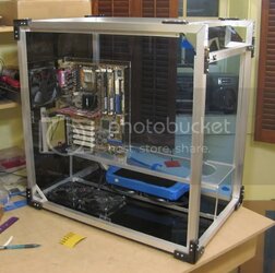
And on the inside:
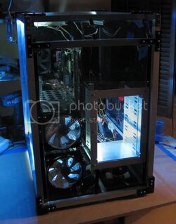
Bottompanelcompletedinterior.jpg
 
Nice work.

You can find the brackets you used on the corners in the lumber section of Home Depot and Lowe's usually. They're made of galvanized steel so you'll have to do some work to make them pretty but they do exist.
 
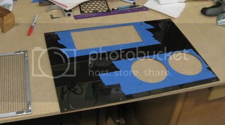
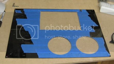
Went to work on the upper panel, which has the same general layout as the bottom panel:


Toppanelcutouts.jpg


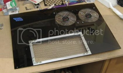
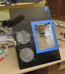
Here I added on the trim and fans:


Toppanelassembled.jpg


Since the top doesn't need dust filtering, I used a nice little grill I constructed from aluminum and modder's mesh.


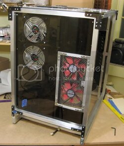
Mounted up:


Toppanelmounted.jpg
 
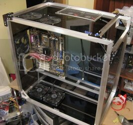
Here it is in place:


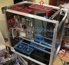
Toppanelairflow.jpg


And a little illustration to redemonstrate my airflow concept:


Toppanelairflowlabel.jpg
 
nice work, do you know about how long it took and about how much it cost??
 
I probably put in around 4 hours per week on this project. It's been what about 10 weeks now, so that would be about 40 hours. That seems a little short maybe 50 hours now.

The cost is in the range of $200.

I should be done in maybe 3 more hours of work technically. That is I will be done with a complete ready-to-be-sold case only.

It'll probably take another 10 hours to set up all the fans, fan control, and install a real system with my water cooling loop.

navig
 
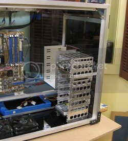
Put together my hard drive rack:


Harddriverackinstalled.jpg


This is comprised of a Lian Li 6 drive rack topped with a 3 drive rack, both available at performance-pcs.

There are 4 screws in the bottom mounting it to the bottom panel, plus the bracket near the top portion that prevents it from swaying.


Then I carved out the last panel, the front panel:


Frontpanelcutout.jpg


And with the fans added and the 5.25 bay:


Frontpaneltrimmed.jpg
 
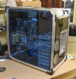
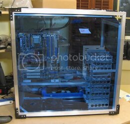
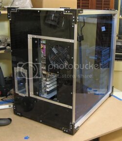
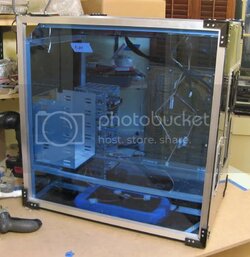
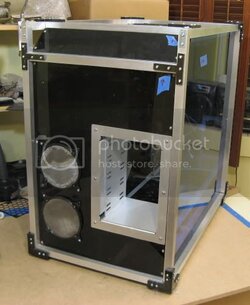
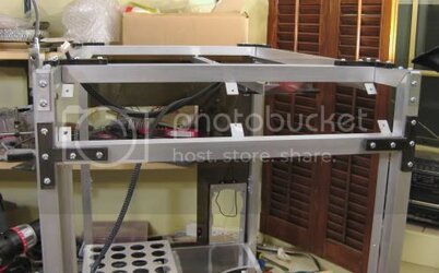
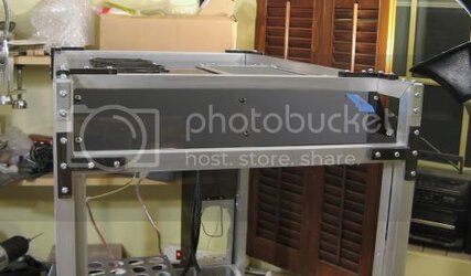
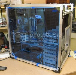
Well, the shell and all the major structural components are complete. I decided to step back and take some overall pics to show how far I've come:


Panelscompleteleftfront.jpg


Panelscompleteleftsquare.jpg


Panelscompleteback.jpg


Panelscompleteright.jpg


Panelscompletefrontright.jpg


Next step: Switching panel and lighting.
 
Added some tabs to firm up this panel:


Centertabs.jpg


Centertabs2.jpg


This panel needs to be nice and stiff because I'm going to put my switching panel here. You want a nice firm push to the buttons, without any give.
 
Here is my first stab at lighting this monster:


Unlit:


Lightingtest2.jpg


Lit from the side:

Lightingtest1.jpg


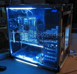
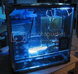
I've got 2 12" white ccfls, mounted up top and down bottom. With the big panels, it comes out nice and evenly lit.


Lightingtest3.jpg

Altho in contrast to the light blue side panels, the other panels are still semi-translucent.


Lightingtest4.jpg


This back half has a smaller 4" white ccfl to light up the psu, back of the mobo. Also, the watercooling components (rez and pump) will be here.
 
You Sir are an extremely motivated and visionary person. I think most case builders are..the ones that finish that is.
Modding is a 2 hour, maybe weekend project, but building requires pure skill, talent, and devotion. Which reminds me, how do you pace your self to only work on it for 4-5 hours a week. If I am working on something I am pedal to the floor and it consumes me. Hence the wife limiting my projects.
 
I love what I do. Experience helps me pace myself appropriately--if you count my benching stations, I've completed something in the range of 20 scratch build projects. To pace myself I set a minor goal that'll take me approximately an hour (for example, arranging the ccfls with tape).

I also multitask, so I always have 1 or 2 1 hour tasks sitting about in my head. As I've mentioned, I'm also simultaneously working on 2 scratch built benching stations.

So for example, on this evening's agenda I have 2 1 hour tasks in mind. For this project, I plan to paint my ccfl invertor boxes, and to possibly hard-mount the ccfls in their appropriate spots. For my station project, I plan to cut my main mounting boards and set them up for routing.

My next 2 steps would be to wire my switching panel (that'd be a 2 hour task).

So on and so forth. I've usually got about 4-5 next steps laid out in my head. The trick is also to know when you've got to order stuff. So for example, I know I have enough tasks to occupy me for another 1-2 weeks, but I'll have to get on ordering some watercooling equipment soon.


navig
 
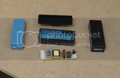
And so, here are the painted invertors:


CCFLinvertor.jpg


I used vinyl dye. Who decided baby blue should be the original color?
 
Well, I've been a little busy of late. Traveling, and a bit of a push to finish some benching stations.


The pace should pick up, as I plan to finish (and have a fully running q6600 system) running before the holidays.


Mini update:


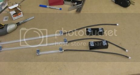
Sleeved and installed my CCFLs.


CCFLsprepd.jpg


Next, I will wire up the CCFLs to their switch, as well as install and wire up my switching panel.
 
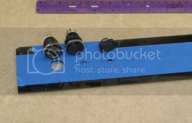
Working on the switch placement:


Switchpanel1.jpg


Going with 2 lit vandals and a toggle. The first vandal has a white LED which will be power-on. The second vandal has a purple LED which will be hard drive activity. The toggle will turn on/off the internal ccfls.


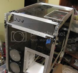
And installed:

Switchpanel2.jpg


I wanted to place the switches to line up with the 120mm fan intakes below. But now that I look at it, I think I should have clustered them a little closer.
 
Now that I've got the buttons in place, I've been struggling on how to wire this beast up.

Every panel is translucent, so there is a 360 degree of view of everything inside. Which means cabling must be squeaky clean, or it will look cluttered. Not only that, this case is enormous, so standard lengths of wire to the switches (and ccfls and fans) aren't going to cut it.


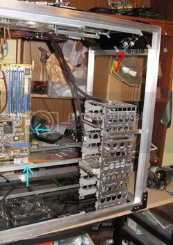
Switchcableroute1.jpg


Regarding the switches, I must get route 10 wires (2 for the ccfls, 2 for the power switch, 2 for the reset switch, 2 for the power led and 2 for the hdd led) from the red arrow to the blue arrows.

You can see that I started to string out some wire, having it hug close to the bracketry.
 
Back