• Welcome to Overclockers Forums! Join us to reply in threads, receive reduced ads, and to customize your site experience!

Water Cooled Framer Project

Overclockers is supported by our readers. When you click a link to make a purchase, we may earn a commission. Learn More.
And then it dawned on me. I've got a completely disassemble-able frame made from tubular aluminum. Why not route the wires right through the frame?


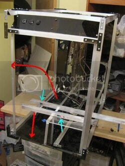
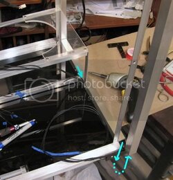
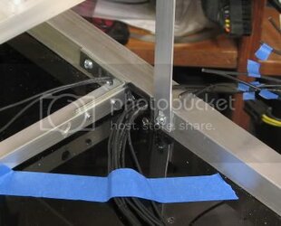
The first step was to remove the necessary frame bars and punch some holes into them:


Switchcablerouteholes.jpg


The light blue arrows point to the holes I punched out. The red arrows indicate where the bar originally came from. As you can see, this would be nearly impossible without being able to disassemble the frame.


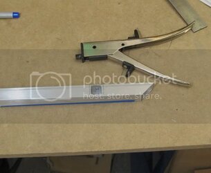
The holes were made with: good ol' nibbler tool, then sanded to a dull edge:


Switchcableroutenibbler.jpg
 
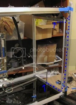
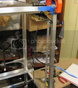
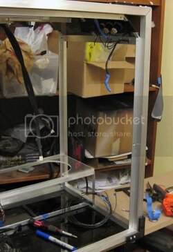
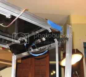
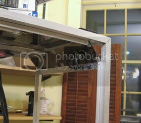
Finally, I threaded a test wire through the whole route:


Switchcableroute2.jpg


The detail is a little hard to see, so I've highlited it, then terminations indicated at the arrows. I'll probably terminate with some quick disconnects, so that the panel can be removed easily if necessary.

As you can see, again, this wouldn't be possible without disassembling the frame. The vertical bar is unattached and that is the only way to thread the wire thru the 90 degree turns.

And there you go. Completely hidden wiring!
 
I order so many things from mcmaster, thank goodness they keep a record of my past orders.


mcmaster part#93085K671
Adhesive Back Foam Rubber Bulb Seal 3/8" O'all Width, 7/32" O'all Height, 10'Length
 
Awesome case. I may do something similar in terms of construction for my next case build.
 
Good luck. I think a pretty big theme to this build is that it is mostly DIY. I'm using only basic power tools and widely available parts.


Here are some pictures illustrating how I work my internal wiring:


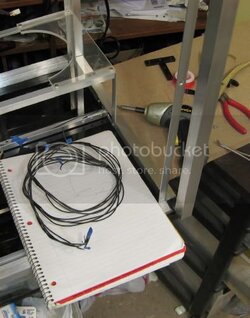
First I built a wire bundle. There are 3 bundles comprised of 22 AWG wire. The first contains the 2 leads to the CCFLs and the toggle, the 2nd contains 4 wires to the power switch/power LED, and the 3rd contains 4 wires to the reset switch/HDD LED.

Cablebundle.jpg


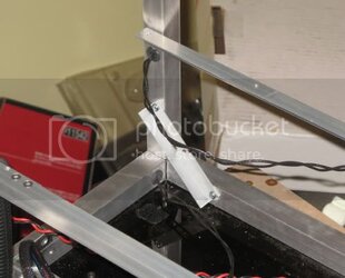
I feed it thru the small end holes at the bottom of the case, down the horizontal bar. The vertical bar has been displaced so that I can grab the end as it comes thru. Then I send it up vertically thru the vertical bar.


Cablefeed1labeled.jpg


It comes out this small hole at the level of the top horizontal bar, then I send it down to the exit holes:


Cablefeed2.jpg


Finally, I can re-mount the vertical bar and pull the wires taught:


Cablefeed3.jpg


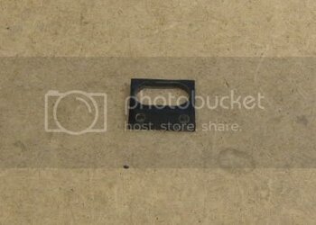
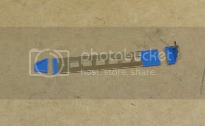
I decided it wouldn't be a good idea to have the cables running thru these fairly sharp holes in the aluminum, so for the bottom hole, I made a little plastic trim tab:

Trimbezel.jpg


Which goes here:

Cablefeedplastictrim.jpg


For the holes at the top, I might also make a trim plate, but I also have some rubber pass-thru's in the mail I might try. I can't really finish the wiring until these arrive and I decide.
 
Okay, finished up the wiring in this corner of the case:


You've got to be careful about finishing the wiring. Dozens of wires, multiple layers of mesh and heatshrink, rubber gromets have to all be assembled in the correct order.

Switchpanelfinalwiring1.jpg


And here is a quick pic of the final product:

Switchpanelfinalwiring2.jpg


Nice, simple and understated. Generally I want the wiring to not be noticed, leaving the overall image to be clean and tidy. But when you start looking for the cabling, you're going to realize it is truly hidden.
 
Here's a little trick I've used to build a fan multiplier.


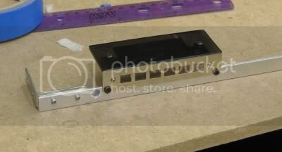
Here I start with a standard easily available pci pass thru bracket:

Fanmultiplier1.jpg


Trim the edges:

Fanmultiplier2.jpg


Add a top cover and mount:

Fanmultiplier4.jpg


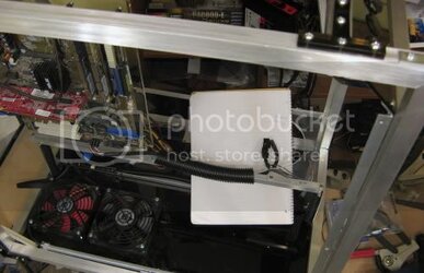
And here it is in the case:

Fanmultiplier5.jpg


As you can see, its very unobtrusive, yet has plugs for 6 fans (as you can see I will be using 2 for the inflow fans, and 4 for push-pull on my 2x120 radiator). Furthermore, I don't have to do any sort of crazy modifications to my fans--simple standard 3 pin terminations.


.
 
Okay, now I've moved onto the wiring on the backside of this case:


Here you can see where the wires for the upper CCFLs and the fan multiplier for the upper bank of fans enters the frame:


Wiringbacksidetop.jpg


Wiringbacksidebottom2.jpg

And here is where they exit.

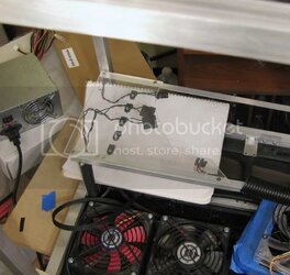
I'm going to mount several terminations (upper fan multiplier, lower fan multiplier, and ccfls, probably even the power connections for 5.25 devices and hard drives) on the underside of the panel that supports the psu (which has been removed in this picture). This is a nice place, close to the psu, yet tucked away and hidden.


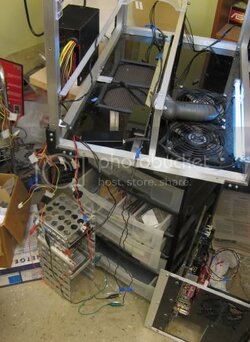
Here I am testing the connections. Just look at that tangle of wires, and you can see what kind of wiring harness I'm building (and trying to cable neatly).


Wiringtest1.jpg
 
And here is my first test of the fully wired and cleaned cabling for the CCFLs:


CCFLsframelit.jpg


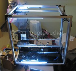
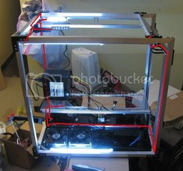
To give you an idea of what this took, I hilighted all the wires for the CCFL system here:


CCFLsframelitlabeled.jpg
 
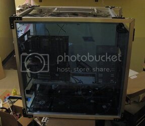
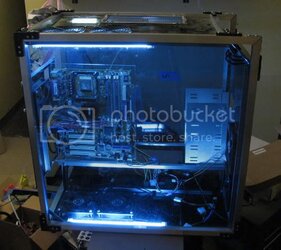
I quickly slapped a few of the panels back on to give you the effect I was trying to achieve:


In the dark:

CCFLstestunlit.jpg


Then lit up:

CCFLstestlit.jpg


And a real time video of that action:

th_CCFLtest1.jpg
 
Starting in on details now.


Switchpanelconnect.jpg

Linked up all the wires coming from the switching panel to the wires from the motherboard panel. Used an 8 pin psu interconnect.


I mentioned before that I was going to use the space underneath the PSU support panel to organize cables: these are nice "p" shaped cable clips:

PSUcableorganization.jpg


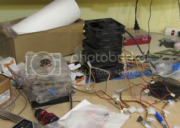
And here are some stacks of fans I've got to sleeve!

Fanstack.jpg
 
what is the best way to sleeve fans???

I am a fan of everything you have done! this is great. probably one of my dreams/goals someday. to actually build my own case, have control and mod everything. it would be amazing.

Everything looks great!!!! :D


keep it up
 
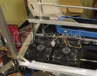
Okay, finished sleeving and installing this bank of fans.

That's six fans crammed together, with easy access to disconnect any one.


Sixfansbottombank.jpg
 
And here is the upper bank of fans:


Topbankfans.jpg


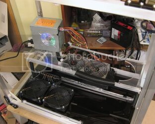
I had to take this radiator from my first watercooling loop. Don't feel bad for this system--since I took off the watercooling loop, its now sporting a Thermalright Ultra 120 copper. This heatsink rivals decent watercooling, both in performance and price.

I should mention, that this project will progress a little slowly over the next week, as I am going to take the time and review the Ultra 120 copper. Then the q6600, IP35-E, and G80 8800gts will migrate to this case.
 
Back