• Welcome to Overclockers Forums! Join us to reply in threads, receive reduced ads, and to customize your site experience!

Sub-zero benching station

Overclockers is supported by our readers. When you click a link to make a purchase, we may earn a commission. Learn More.

torin3

Member
Joined
Dec 25, 2004
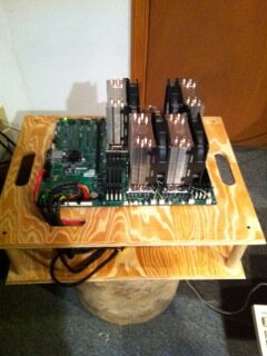
I've already built one benching station for my media server/main folding computer. And now that I've got a dry ice / LN2 pot, I figured it was time to make a new benching station.

Time to head out to the shop. Uh...looks like my workbench is a bit messy...

benchc1.jpg

I really haven't spent much time out here since it got cold. About the only project I've worked on is this one:

stove1.jpg

Now that the fireplace is done, I can actually work out here without gloves.

Anyway, on to the project.

Here are the legs. Two are longer so that I can anchor the cards off of the motherboard. The L-brackets are from McMaster-Carr. However this is the second time I've ordered them, and I'm getting really tired of them arriving with stickers on each and every one. And they are old enough that the stickers come off, and leave the dried up glue on the brackets. Some paint thinner takes care of that, but it does take a bit of work. I'm using aluminum pop-rivets from Lowes. They are the 3/16" diameter ones, and a mix of 1/8" gripping range and 1/4" gripping range. I got the 1/4" ones by mistake. They do work, but on some of them I have to file down some of the excess length on them so they will all fit.

benchc2.jpg

The legs are sitting on top of 2 sheets of 1/2" plywood. They are 2'x2' square. They are a bit large for a benching station, but if I leave them that size, I don't have to fire up the table saw and worry about having an uneven cut. Plus it will give me extra space to place the DMM that I'll eventually use to measure my temps.

Here is the U-channel that I'm going to use over the edges of the plywood. It will let me drill and tap holes for 6-32 screws. I like the U-channel because I don't have to worry about the screws ripping out of the wood. 1/2" plywood isn't that thick, and drilling for holes can take up a decent chunk of that thickness.

benchc3.jpg

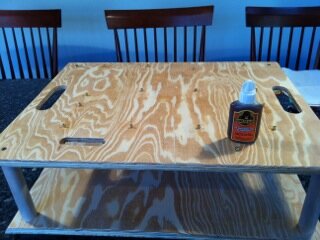
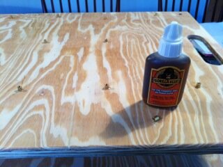
And since I'm going to be dealing with cold temperatures and potential spills, I figure I should seal up the plywood. Here it is after 1 coat of gloss poly. I'll give 2 coats on each side. I've already got 1 side done tonight, and I'll get the other side tomorrow after work.

benchc4.jpg

I'm hoping to have this done by the end of the week so I can start playing around with it before the next round of Forum Wars. I may wait a bit to get the hard drive cage and a few accessories. I've got just about all I need to put it together now.
 
Well, the boards are flipped over, and have the first of 2 coats of poly on them. Looks pretty much the same, so no pictures. I should have more tomorrow, as I'll be starting to drill and tap the aluminum u-channel.
 
Ok, the poly is on and dry. Time to glue on the edging. I was going to use Gorilla glue, but my bottle had hardened to a solid cylinder. I didn't think the wood glue would work that well on aluminum, so I went with the epoxy:

benchc5.jpg

Then, since it wasn't all that warm in the garage, I put them next to the fireplace to cure. (Warm epoxy cures much faster.)

benchc6.jpg

benchc7.jpg

And once it had set up enough that the edging wasn't going to slide off, it was time to drill and tap them. I'm using 6-32 thread for most of this station, as it is the standard screw size for most computer screws. I used a 7/64" drill bit (which is the right size for tapping this thread), and the hand tapped the hole. A note here. I'm using 1/16" thick edging. I wouldn't want to go any thinner, because I'm barely geting 2 complete threads in it using this tap. Screw size designations come in 2 parts. The first number is the diamater of the screw, and the second number is the threads-per-inch. 6-32 has 1 thread ever 1/32nd of an inch.

benchc8.jpg

benchc9.jpg

Once they were all done, I screwed the pieces together. This will also help hold everything in place while the epoxy cures. I brought it in to help with that. Now we are down to fine details. Where to put the motherboard and drill the through holes for mounting it. And the power supply an other attachments. (Drives, fans, etc..)

benchc10.jpg

benchc11.jpg

Oh, the last benching station I built was 16"x18". That gives you 288 square inches per layer. On this one, since it is 24"x24" I actually have exactly double the amount of space. 576 square inches per layer. I shouldn't have any problems getting things to fit.
 
Working out in the garage again. Just stopping in to fill up the Zune with podcasts.

I should have more pictures up sometime this weekend. I'm working on mounting the motherboard now.
 
Looking Great there torin3, like the C-Channel edging.

Building another Tech Bench myself too at the moment!
 
Thanks Jolly!

Anyway, time to start mounting up the motherboard. I've cut tabs out of the 3/4" x 3/4" x 1/8" angle aluminum.

benchc12.jpg

To get the motherboard at the right height, I've mounted the well nuts onto the board upside down (this lets me use shorter screws, and helps avoid scruching down the nuts if I over tightened them).

benchc13.jpg

Now time for drilling and tapping the angle aluminum I'm using for the screwdown bar for the expansion cards. I forgot to take a picture, but I put the cards in the motherboard, then placed the motherboard where I wanted it, and then positioned the angle aluminum so that it was snug to the cards and then marked where the holes needed to be drilled. After drilling comes the tapping.

benchc14.jpg

Again, I missed a picture I should have taken. I screwd the angle aluminum to the cards and then place the whole assembly back onto the benching station. Held the angle in place with some C-clamps, and then drilled through holes through the angle and the square tubing with a 1/8" bit. Then I removed the angle, and redrilled the tubing with a 9/64" bit, which is just large enough for the 6-32 thread to fit through. A 5/32" bit would have worked as well too. Then I used a 7/64" bit on the hole in the angle for tapping. When all was done and it was screwed together, it looks like this:

benchc15.jpg

The nice thing about this is I don't even need a nut to hold it in place, as the threaded hole on the angle works great for that.

And a couple of quick close-up with it in position.

benchc16.jpg

benchc17.jpg

And here are some closeups of the well nuts working as standoffs.

benchc18.jpg

benchc19.jpg

After that, I removed the well nuts one at a time, and center punched and then drilled a through hole for the mounting screws. However I managed to screw it up just a bit. The motherboard is a bit angled to the edge of the benching station. :bang head Everything still works fine, but it looks just a bit off.

Next time I think I'll print out a scale size drawing of the holes and centerpunch them first.

Anyway, I decided to call it a night. Tomorrow, I'll mount the PSU and drill and cut the pass-throughs for the cabling. I'm not going to worry about the optical and hard drive mounting cages yet, but I'll make something for them in the next few weeks, but it will be usable as of tomorrow.
 
Ok, time to remove the motherboard to drill the through holes:

benchc20.jpg

I drilled the holes with a spade bit, since I couldn't find my forstner bit. Rougher holes, but it got the job done.

benchc21.jpg

Then it was time to cut the slots with the saber saw. Piece of advice, don't try and touch up an edge if you've got less than 1/8" you want to cut off.

benchc22.jpg

And finally, I put in the bars for the PSU. Cut the angle aluminum to length, drill the holes for the PSU mounting, then place it on the benching station and drill holes through the mounting angle aluminum to the c-channel. Tap the c-channel, and then drill slightly larger holes on the angle.

And here you are:

benchc23.jpg

I need to assemble the system and then I'll take a final picture.
 
Well, I've had it together and running for a while now. Here is what it looks like:

benchc23-1.jpg

I think it may be just a bit too big. I think I'm going to pick up a saber saw that can keep the blade perpendicular (unlike my current one), and use that to saw down the next one to a little more reasonable proportions. The 16" x 18" one I made before is a little snug, so maybe 20" x 20" would be more reasonable. It would also save me about 2 feet of the U-channel aluminum.

I'm going to be adding a few more things, but this should do for now. I figure rather than a hard drive cage, I'll use some L-channel to mount the hard drive.
 
Ahh just the thread I was looking for... I was wondering whether folks used a plunge router or did what you did...I'll use my forstner's.

Torin I am not familiar with those well nuts...what are they and where do they come from? Also did you make the edges or does some one carry them(Oh never mind on this one I reread your thread)? I used my router on my edges just for looks. I am just going to use four square wood post at the corners. One last question did you make the distance between your layers custom or is there a standard height? I was guessing at 8".

Thanks for the info
 
Last edited:
Ahh just the thread I was looking for... I was wondering whether folks used a plunge router or did what you did...I'll use my forstner's.

Torin I am not familiar with those well nuts...what are they and where do they come from? Also did you make the edges or does some one carry them(Oh never mind on this one I reread your thread)? I used my router on my edges just for looks. I am just going to use four square wood post at the corners. One last question did you make the distance between your layers custom or is there a standard height? I was guessing at 8".

Thanks for the info

I get them from McMaster-Carr, and they run about $14 for 25 of them. The part number is 93495A120 They are really designed to be a screw through rivet, but they work great as stand-offs.

Also, I just went with what I thought would be good for a space between upper and lower levels. As long as you can fit your power supply and drives (and water pump, etc...), go with what height you like. Too much, and it gets hard to connect up the cables for power and drives.

That what you needed?
 
Thanks T,

I am still deciding on whether to sink stand offs into the wood or order some of these well nuts. Can you clarify something for me?

I see the well nut on the board with the screw coming out, I am assuming that screw runs up from the bottom and I get how that works...but then I see when the Mobo is in place instead of nuts(like I would have thought) you seem to have the normal screws, how does that work?
Thanks:beer:

Warning, crappy ASCII art coming up:

Code:
___        ___
   ||    ||
   ||    ||
   ||>  <||
   ||>  <||
   ||>  <||
Ok, this is a cut-away view with the flange at the top. There is a threaded brass insert at one end. You put that against the surface of your benching station. You have a hole drilled throug the board large enough for your screw. When you thread it through the well nut, it holds the screw and nut in place. Long enough screw, and the threaded end sticks out the top of the well nut. The well nut still has about 1/2 its height with just rubber, so that provides cushoning for the board, and the flange is wide enough it provides a good contact point for the board. I just use 6-32 threaded nylon nuts to hold the board onto the well nuts.

If this doesn't help, I'll try and take some very close up pictures for you.
 
ahh OK those pis in Post #8 threw me...you just had the well nuts on temporary and then switched to the final screws in Post #9. This looks like an easier way then embedding nuts/standoffs in the plywood.
Thanks again.

I did just get your skype message, I am complete fail at getting that thing to notify me on my phone.:eek:
 
Last edited:
ahh OK those pis in Post #8 threw me...you just had the well nuts on temporary and then switched to the final screws in Post #9. This looks like an easier way then embedding nuts/standoffs in the plywood.
Thanks again.

I did just get your skype message, I am complete fail at getting that thing to notify me on my phone.:eek:

No problem. Hope it works out well for you. Good luck! :thup:

Edit: Just went back and looked at my photos again. Yeah, I had the well nuts upsidedown in the first few pictures. Sorry about that.
 
Nice station torin, high-quality stuff :thup:

@dfonda

You can get the well nuts at places like Lowe's and Home Depot too. That's where I get mine for my stations (Cu, PVC).

1zx5gqp.jpg

I also just use nylon screws that go through the wood and the well nut. Then I can just set the motherboard on the well nuts and the nylon screws hold the board in place. That makes the board easy to remove since I don't have to unscrew anything. Since I change boards often, that's a huge plus for me.

2z8oydg.jpg
 
Matt where the heck did you find those? I searched Home depot's screw section and all the drawers where the odd plastic spacers are etc. for an hour and couldn't find them. Are they in some other section? Plumbing?

I know Lowe's around me often has things that HDepot doesn't, I'll go search there, give me a hint as to what section they are in! I may have picked the wrong salesperson to ask, they were stumped. Some of the folks no where everything is in the whole store.

By the the way that's about $150 worth of copper at current market value!:p Looks good though!
 
Last edited:
That's section I find them at. I've gotten well nuts from both stores in their hardware section where all the drawers full of screws, bolts, nuts, etc. are located. Same for the nylon screws.
 
Incredibly I finally found them at Lowes...except not in my size and no where near 14. So tried McMaster, couldn't get the order to acccept. Used the part # at W.W. Graingers, $14 but over $9 shipping.:eek:

I ended up using common Standoffs. The holes I had drilled were tight enough to allow the threads to pull in tight and Gorilla Glue did the rest. (First time I ever used it) I had my over/under at 2 for standoffs not matching, figured 14 was a lot of holes to keep aligned...I was just going to knock them off...Luckily Hit them all.:thup:
 

Attachments

  • Budget4.jpg
    Budget4.jpg
    31.9 KB · Views: 360
  • Budget2.jpg
    Budget2.jpg
    34 KB · Views: 359
  • Budget1.jpg
    Budget1.jpg
    32.3 KB · Views: 364
Last edited:
Back