• Welcome to Overclockers Forums! Join us to reply in threads, receive reduced ads, and to customize your site experience!

PROJECT LOG Project R Unit

Overclockers is supported by our readers. When you click a link to make a purchase, we may earn a commission. Learn More.
Hallo! I am back and modding in full force!


jwalker. I try to make my project logs as detailed as possible, and I will answer any questions posted. Unfortunately a lot of my previous posts disappeared with the collapse of abit, RIP, and its forums. I have made a link set of what remains and am in the process of reposting what I can.

My mod links.

I get most of my modding stuff from performance-pcs. I shop around to find aesthetics stuff from sites like svc, jab-tech, crazypc, and xoxide.


Okay, everybody, sorry for the hiatus, but the shop is setup and modding again.


So, back to the Project R unit, and lets move forward.

The next task I wished to tackle was to see if it was possible to implement a self-opening system for my plastic front lid.

First I purchased a gas spring self-opening piston with the least amount of force I could find (5 lbs), from mcmaster. But it became pretty clear to me that this might involve some significant adjusting and geometry. I didn’t really want to put too many holes into my current build (altho not too difficult to repair).

In the past I’ve had some difficulties in a similar situation. For my Jewel Box Project, I was working on a method on having my lid open to a particular angle:

See post#35.

I ended up implementing a chain stop that ultimately failed, leaving me holes in my beautiful plastic lid.

Now MDF is very easy to repair, but I was not at all certain my plans for a self opening system would even work at all.


So what to do?

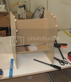
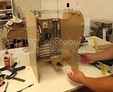
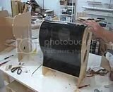
The simple answer, build a mockup. Since I’ve got templates and exact measures of all the pieces, building a quick and dirty replica took barely any time at all:


Mockupstarted.jpg

This was put together with some thin ¼” MDF and spare crossbars. The side pieces represent the outermost edge, the little round pieces space holders for the inner lip.


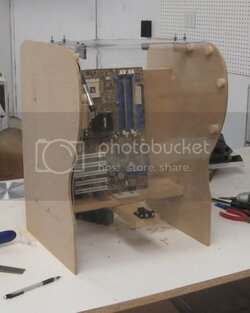
Next I fitted the plastic lid to the mockup, hinged with a pair of simple hinges at the top:

Mockup1.jpg

I also installed a push-to-open latch at the bottom to latch to lid in the down position.


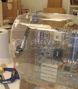
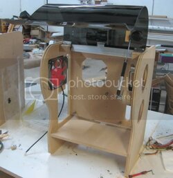
Next I installed the piston rig.

Pistonassembly1.jpg

The rig consists of a mount base with a pin, the piston, then a mount for the plastic lid.


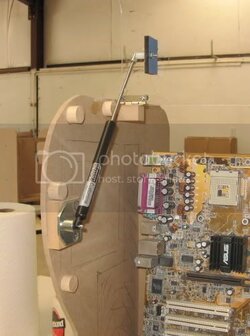
And does it work?

You betcha! Here it is in the open position:

Pistonassembly2.jpg

The movement is brisk but controlled, the force of the push a little stronger than necessary but hardly difficult.


Here is a video of the action in, well, action:

th_Mockuplidopen.jpg

Its a photobucket link, somebody let me know if it doesn't work.


I am quite pleased—this was a fairly large hurdle overcome. I did have a backup plan (simple friction hinges, as in how laptop screens stay open). But this has such a cool factor!


.
 
That is just cheapo acrylic from Home Depot (I believe it measures .18"). There are 2 kinds of typical sheet plastic out there, if you didn't know--acrylic and polycarbonate. Polycarbonate is a bit nicer to work with, but won't bend easily.

I'm using the cheap plastic right now just to make sure things work out all right. I will use high quality 1/4" gray smoked acrylic for the final product. I get me plastic from delvies.

Thanks. http://www.delviesplastics.com/ I was looking at but there pricing is so cheap I was not sure if something was wrong. Extruded pricing with cell cast quality scared me from buying which I think is safe to try now.

You used a heatgun on the plastic and a form to get it this way correct?

I used a heat gun at one point but ended up heating it up to much or not enough and turned to using a low temperature portable heater from a distance.
 
Forming the plastic--nope I popped it in the oven. It would be pretty difficult to evenly heat such a large sheet. I keep a close watch on the plastic temp with an IR thermometer. For this plastic, when my IR thermometer gets to about 250F its ready to be molded.

I will use a heat gun if I need to slightly mold isolated spots and deformities.
 
Now that I’ve proven that the overall design should work, time to get back onto the proper piece.

First I took the time to start carving up the panels for fans: I’m going for 2 120mm intake fans, and 1 120mm exhaust (plus a 220 or 250mm fan exhaust up top).

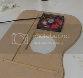
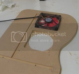
Making fan mounts in ½” mdf is not as simple as metal or plastic. It looks a little goofy to surface mount the fans as wall material is so thick, so I sink the fans into the mdf like so:

Fanholescut2.jpg


This is a technique I’ve used a lot. I mentioned it above when I created the under-cpu –socket fan mount, altho I decided to use a normal circular cut-out instead of the octagonal one above.


1) Step one is to go ahead cut out the circular hole with a hole cutter or hole saw.


Fanholescut1.jpg


2) Step 2 is to mill out the square form to sink the frame of the fan into the mdf.

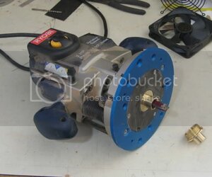
3) The tools necessary are a router with a depth stop, and a router plate with a guide bushing.


Routerplate.jpg


The router is a cheap Ryobi $70. The router plate is the blue plate attached to its bottom, and the guide bushing is brass knob thing.

The router is fitted with a ½” diameter straight cut bit. I’ve selected a guide bushing with ¾” outer diameter. If you keep track of the math, that means the router bit will cut out an edge 1/8” smaller than the guide bushing.

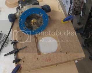
So I created a jig which is a cutout that is exactly the shape of a 120mm fan but +1/8” larger.

Thus, the guide bushing will be guided by the edge of the jig, but the end will be a hole the exact shape of a 120mm fan.

4) So I next secured the jig over the circular hole, centered.

5) Next I set the depth stop to be 3/8” deeper than the surface of the mdf panel.

6) Then I carefully route out the shape of the fan.


Cuttingfanholes.jpg


In this picture, you can see the circle cutter I use on the left.
The jig is secured to the panel.
You can see the edge of the square cut out, 1/8” smaller than the jig.
At the bottom is the round hole.


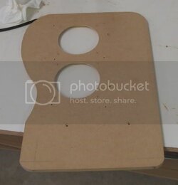
And this is the final sunken fan cutout:

Fanholescut2.jpg


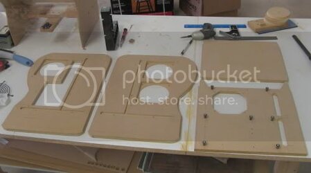
Here are the panels after I got done cutting the fan holes:

Afterfanholescut.jpg


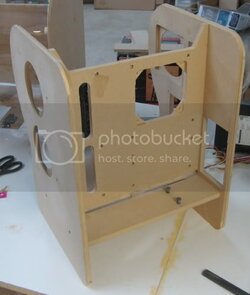
This is the entire structure of this case—4 fairly intricate cut pieces of mdf.


.
 
I have handled the tools you have and just messed around. Your workmanship is amazing.

Time to make custom cases for the rest of us :)
 
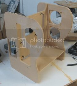
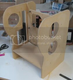
And here are the MDF components assembled.

MDFassembled1.jpg


MDFassembled2.jpg


And also, I’ve added the power supply cutout.

MDFassembled3.jpg


Then I switched back to the plastic work. Using some ¼” dark gray sheet acrylic, I baked it up in my oven until it was just pliable. I set the oven to 265F, and measured the surface temp of the acrylic. When it hit about 245F, I knew the plastic would be getting supple. You have to be very careful—go too far and the plastic starts to emit ominous fumes, as well as becoming almost gooey in nature.

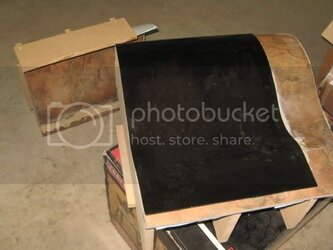
Then I flopped out the plastic onto my press form:

PlasticPress1.jpg


The top (which is in the background) goes on top, pressing the plastic (it will change its shape as it cools so you’ve got to have it fully pressed). Wait to cool, and there you’ve got a bent sheet of plastic.


The press form wasn’t perfect, but I was able to smooth out some imperfections with some rolling pins and a heat gun.


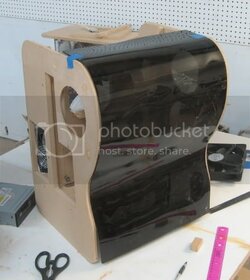
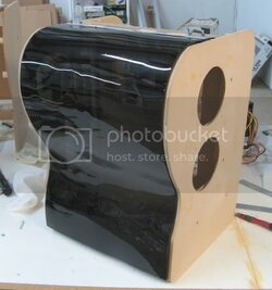
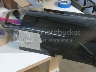
And here is the plastic on the case:

Plasticfrontpaneltapedon.jpg
 
Great work Navig and really unique ideas! I'm pretty new to the computer world (at least the technical part) but know my recent computer will be the last one I buy. I'm making my own from here on and your threads -and others on this forum - show me I can also be creative for my next (and first) build.

In the meantime, I have been a custom furniture and cabinet maker for many years. Your work is excellent -honestly- but maybe I can share a couple tips I've picked up. No offense is meant and honestly, I know most of these when more experienced people I have worked with showed me.

First, when working with MDF, BONDO is your friend. MDF, while a wood product, is essentially simply a base for acrylic or lacquer paint products. As such, autobody painting rules apply. The edges of MDF and any holes should be filled with bond, then sanded smooth. Don't be afraid to use multiple layers of bondo as it shrinks as it dries, and it dries faster when thin. Also, bondo will transfer through the paint less than will wood filler. Lastly, spot apply a few layers of primer/lacquer/etc to the edges and any other filled places then sand them smooth before priming and painting the while thing.

Use big, flat blocks when sanding so its super smooth and will not show a bump or dip through the paint. Same applies for the edges adn curved edges. For curves, use a piece of 1/16" or 1/8" 3-ply sheet (about 2x6") with grain running the short way. Wrap your paper around that and it will smooth off very nicely and very evenly.

And to that end, do yourself a favor if your making forms or other curved stuff, contact your local cabinet sheet-goods supplier and get a few sheets of 3ply 1/16" and 1/8" (probably sold in mm now). These will bend super smooth as they are engineered to be very consistant and bend smoothly.

Fill the spaces in your forms with the higher density pink foam insulation used for house construction. You can use the same template and router techniques to shape it. It is dense enough to really fill those spaces up and can handle quite a bit of pressure without compressing if you limit it to about 4" wide. I used to use this technique in vacuum bags all the time. I'd cover that form with a layer of the 1/16" 3ply as it is very smooth and thus won't transfer or telegraph anything to the plastic. If you wanted a wood front, use your forms to press and glue (Gorilla glue is best here) 2-3 layers of the 1/16". Be aware that if you go this route, it will spring back a little so make your curved panels then shape your sides to fit. In fact, that is the best way to do any curved work.

When you make your top form, make it smaller by the thickness of the material you are forming or the forms won't match up in the bottoms of the curves. Same goes for making the bottom form from the side templates. Any skin you add has thickness and will prevent the final piece from fitting the sides perfectly (partly why curves always made first when possible). For the bottom, the best way to do this is to use the side template to make 1 of your form ribs, then use your router to rabbit it back the thickness of your skin, then a flush bit to flush off the rabbit lip - now perfectly x amount smaller along the curve. Make your other ribs off that first one. Do the same for the top rib but rabbit back the first the thickness of you skin plus the piece your bending.

The last thing I would suggest is to recess the I/O part just like you did the case fans. I'd find the extra thickness of the side to be really annoying and the thickness looks a little wierd to me. If your concerned about the strength of the lip, paint the inner parts with thinned out epoxy so it sinks in. If your doing much epoxy work, WestSystem32 is the best in my expereince. Another alternative for the I/O is to route out to give a ~1/8 or thinner lip, then glue in 1/8" maple or poplar (or even MDF) strips. The act of gluing in strips will greatly strengthen that lip.


Again great work! I'm sorry to presume to offer advice but I think lots of people would benefit from these tips. Anyone is free to pick my brain wood related - my way of giving back to a community that has shared so my knowledge with me.

Dennis

(btw: A final though on bending the acrylic. I am not sure but seem to remember it works best if annealed. Heat it once, let it cool, heat it again and allow it to sag form in teh oven, slowly reducing the temp and allowing ot to cool on the form in the oven. The final step may be to heat it again to a lower temperature to temper it and let it cool. I've not done much work with acrylic or polycarbonate but that seems familiar to me).
 
Thanks for all the great info.

Apologies to all, been a bit busy lately. It's been a while since I've made progress, but not because I've not been working on the project. Just got stuck...more in the next posts.


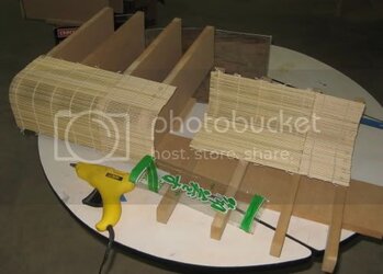
Getting back to bending plastic, I went ahead and constructed the forms to bend the plastic sheet that will form the BACK side to the case. Instead of a compound double curve, this one is just a single bend:


Here is the bending form.

Plasticbacksidemolds.jpg


And yes, that is in fact those bamboo sheets for making sushi rolls. I wasn’t entirely happy with the results of the vinyl sheets. They tended to crack. So I cast about for a solution that would be quite strong in the lateral dimension, yet able to form a planar curve. And was cheap.

I was at a local asian grocery, when I saw these rolling sheets for $3 apiece. As I make rolls on a regular basis, I realized that this just might fit the ticket.

BTW, my specialty roll: smoked salmon, egg, avocado, and furikake.

Anyway, I just hotglued them on, and we’ll see how it goes. I’m not that worried that the ridged texture will come across the plastic—I don’t heat the plastic to the degree that it picks up these sort of patterns.


If it doesn’t work, I think dennisdietz' tip on filling in the voids with polystyrene insulation may really do the trick well. Maybe, if I can find some 1/16" or 1/8th, that would work well too.
 
Next, I switched gears back to the front side of the case.

Remember I had finished fitting my front curved plastic panel; now it was time to attach the panel. Recall that I had planned on having this panel open up, so I had to mount this panel with hinges.

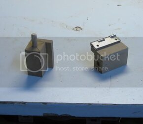
Now in my mock up model, I simply glued some mounting blocks onto the vertical wood panels. But I found out the hard way that this wasn't going to cut it. They broke right off under the stress of the weight of the panel. So I had to strengthen the mount. Once again I borrowed some woodcrafting 101 to strengthen the bond.


I first constructed my mounting blocks from MDF. Then I added a dowel rod peg.


Hingeblocks.jpg


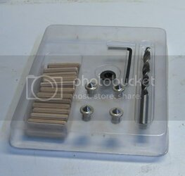
The dowel rod came from a $3 kit from my local Harbor Freight tools:

( Dowelkit.jpg


The kit comes with a 1/4" drill bit and some dowels, plus a depth stop collar (no need for me, I'm using a calibrated drill press) and some pin markers to locate your matching holes.


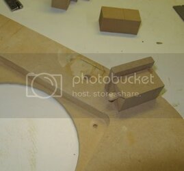
By using the pointed plugs, I could locate the exact location for my matching hole on the vertical panel:

Hingemountingblock.jpg


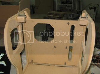
Added glue to the dowel peg and hinge block, and it was nice and sturdy:

Hingesmounted.jpg


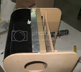
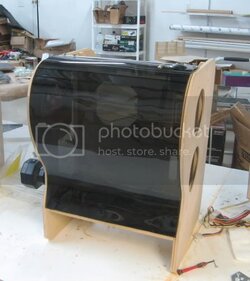
And now the front panel was mounted and hinged:

Hingemountedplasticpanel.jpg


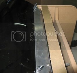
The next thing I did was add a bar of aluminum trim. This serves 2 purposes: it strengthens the mounting points at the hinges so that the screws won’t crack the plastic under stress (essentially acting as a washer). Also it allowed me to mount and under lip trim piece.

Hingeendplate.jpg


Whenever you are working with hinges, you’ll have to deal with gaps (unless you use special hinges). The panel that is moving has to have some clearance from the adjacent panel.

The extra piece of trim will bridge the gap from underneath (in the end all this metal will be painted black), so that the gap won’t be noticeable: here is the hinge in the open position revealing the gap bridging trim:

Hingeendplatelip.jpg


So many details.....
 
Next it was time to mount up my gas springs so that the lid would pop up.

This step turned out to be a struggle of epic magnitude, and what I’ve bee trying to work thru the last few weeks.

On my mock up, a single 5 lb force gas spring worked very nicely.

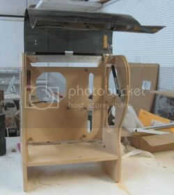
However, when I mounted up the spring on the real deal, it could not deliver enough force to raise the whole panel, the difference being this real panel is thicker and denser plastic.

Thus I lost round #1.


Round#2: so I went ahead and orderd up the next level of force, a 10 lb gas spring.

Turned out this spring delivered too much force, causing the plastic warp on the one side and to pop open with violent force.


Round#3: so I went ahead and ordered a second 5lb gas spring. I then positioned a second gas spring on the other side (if you look at the pic below, you can still see the mounting point), going with double 5 lb gas springs.

The double gas springs did help in not warping the plastic, but the opening was still too violent for me to accept.


Round#4: I experimented with larger and more spread out mounting blocks on the plastic panel to reduce stress on the system, but the opening was still too aggressive.


Round#5: I contacted Industrial Gas Springs, the company that actually makes the springs (I was buying them from McMaster). They could sell me calibrated 3 lb springs, but they would cost $70 apiece.


Round#6: At the suggestion of my wife, I looked into counterweighting the lid panel. After a little experimentation, turns out just a few ounces at the far end of the plastic panel resulted in large differences in the forces required on the gas piston.


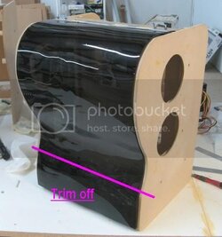
Round#7: This was the AHA! Moment. I realized that I was using this full panel with my gas springs (see picture above), but in the end, the panel would have its end significantly trimmed off because the panel for covering the 5.25 bays was going to be a completely separate panel (and not hinged).

So I trimmed the panel. And lo and behold, the orginial plan of a single sided 5 lb gas spring works perfectly!


Hingemountedplasticpaneltrim.jpg


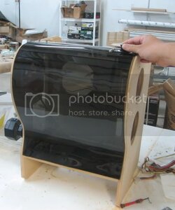
So here is the panel now mounted up with the gas spring:

Lidfinalgasspring.jpg


And here is a video of the smooth action of the gas piston:

th_Gasspringinaction.jpg


Next….I will be working on the latching mechanism.


.
 
Your video isn't cooperating right now, but that's a great story. Glad it worked out. :)

(Shop looks very nice btw!)
 
Maybe the direct link will work better:

Gas spring action test video.


Please let me know if it still ain't working. Apparently its an mp4 hosted on photobucket.


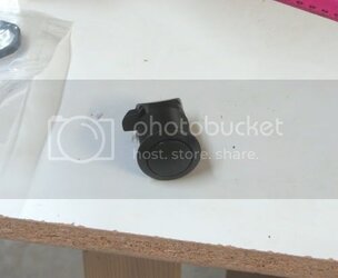
Alright, so this arrived speedily from mcmaster:

Buttonlatch.jpg

This is a stealth push button knob turn latch. Yup!


As in it normally is in a stealth state, flush to the button rim.

Then you push the button and the button pops up and becomes a knob.

Twist the knob and the latch opens.


I hope videos work, because this has to be seen on video!

I first mounted it up on my mockup unit, just to see if it would work, estimate clearances and measurements, etc.


th_Lidlatchtestonmockup.jpg

Please let me know if the video is working!
 
Okay, time to transfer this mechanism from the mockup to the real deal.


First I cut a hole into the plastic panel to mount round latching button:


Lidlatchthruhole-1.jpg


This was actually a little problematic—the plastic at this point (having been heated and cooled mutiple times) is fairly brittle. Additionally, the surface of the plastic is slightly curved. Using a hole saw would likely break the plastic (I know—it cracked my mockup plastic panel).

So I went old school—using my dremel and a cutting blade, I cut a rough polygon of the hole. Then I used the sanding drum and just sanded away a round hole. Yum the taste of acrylic dust.


And here it is mounted up:

Lidlatch1.jpg


Push the button, popping up the twist knob:

Lidlatch2.jpg


And the lid pops open!

Lidlatch3.jpg


I did have to make some functional concessions for this mechanism. You will see that the mounting block for the base of the gas spring is quite tall. This was because I needed the clearance for the latching button to be on this side of the panel. The latching mechanism has got to be on the same side of the gas spring because it has to be near the point of tension, otherwise you will get significant twisting of the plastic panel. Trust me, I tried every combination of location of gas spring/springs, latching mechanisms, and this combination seems to have worked the best.


And here is the video:

th_Openinglidlatchtest.jpg


.
 
Back