• Welcome to Overclockers Forums! Join us to reply in threads, receive reduced ads, and to customize your site experience!

PROJECT LOG Project R Unit

Overclockers is supported by our readers. When you click a link to make a purchase, we may earn a commission. Learn More.

Navig

Senior Case Master
Joined
Dec 7, 2003
Project R Unit


Hi all and welcome to my latest scratch build project. The tentative name is really unimaginative as you will see, but the case is pretty unique if I do say so myself. The inspiration for this project builds upon one of my previous projects (the Console project). I liked the idea of a curved plastic form. Gives a computer case a much more organic feel.


Here were some starting criteria for this project:

1) Going for a slightly smaller size build (as opposed to the Console project or the Exoframe)

2) But must fit a full sized motherboard, large video cards, and tower heatsinks

3) Reproducibility. This is not meant to be some crazy one-off project. If there is some sort of demand for this case, I want to be able to reproduce it at a reasonable cost to money and time.

4) Excellent airflow for full powered pcs.


Sketches

As usual I began with some sketches.

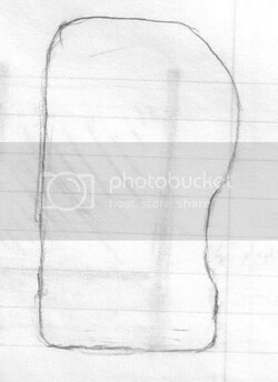
This curve here was the inspiration for my project:

Runitdraw5.jpg


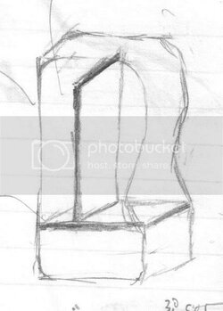
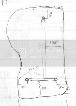
This was the basic structural elements of the case:

Runitdraw2.jpg

I decided on 4 panels of ½” mdf. There are 2 side panels with curved edges that will definte the curved front panel. A structural horizontal panel, that will house the switch panel and 5.25 bay drives below. And a vertical panel, that will also serve to be a motherboard tray.


The entire curved front and back surfaces will be translucent plastic. I almost want to make the whole tower appear to be wrapped in curved plastic


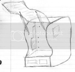
Here is an outward appearance rendition:

Runitdraw1.jpg


Yes, I plan on having the plastic panels swing open (front as pictured, back as well). I am NOT sure that I will use the fancy piston openers—anyone who has worked with them knows what a pain they are (and very costly as they will probably need to be custom crafted).


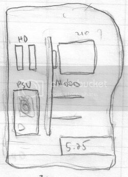
Here are some planning pics:

Runitdraw6.jpg

You can see roughly from this pic how components will lay out.


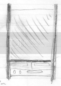
Straight on picture, emphasizing the switch panel and dvd drives:

Runitdraw3.jpg


Runitdraw4.jpg

Dado planning. I am going to mill out dado grooves in the side panels—the horizontal and vertical panels will fit into these grooves lending serious structural stability.


.
 
I see the potential from what you've drawn, I think you should go for it, if you do it right it'll be pretty sick.
 
Always glad to see your threads Navig, you're one to count on for the real product to follow up after the plans are made. Did you ever get my email about misplacing your email for that write up you sent me? Forgive me if I'm just forgetting something, I'll be checking both my mail boxes tonight...
 
the design of having the front panels open up is like the Asus Vento. pretty cool i reckon :thup:

vento3600.jpg

or maybe the Acer Predator?
predator.jpg
 
Yes, I've seen those--unfortunately I'm finding it difficult to find off the shelf hinges to make the nice hydraulic action, but that's a seriously long post for the future.


Okay, once I established the general idea, it was time to hammer out the details to scale.

I started with a paper cutout and laid out my components to make sure everything would fit appropriately:

Sidepanellayout.jpg


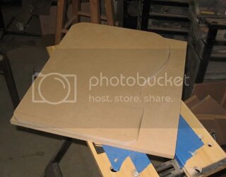
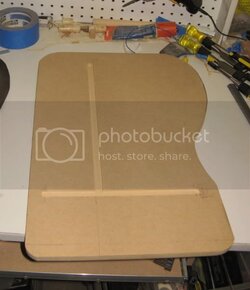
Next I transferred this to a piece of 1/2" mdf.


Then I needed to exactly duplicate this panel
a) for the other side of the case
b) future reproduction.


This was the method I chose.

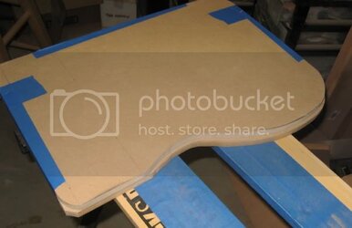
First I took some stock cut down mdf:

Sidepanelduplication1.jpg


Next I rough cut it large with my scrollsaw:

Sidepanelduplication2.jpg


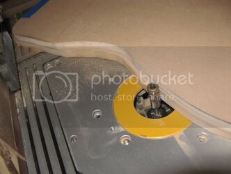
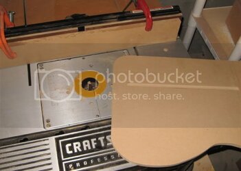
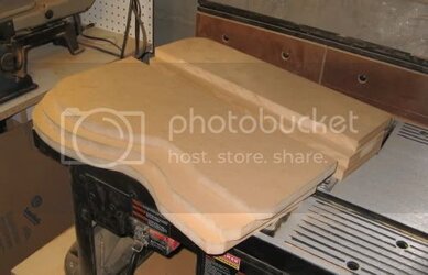
After taping the 2 together, I headed to the router table:

Sidepanelduplication3.jpg


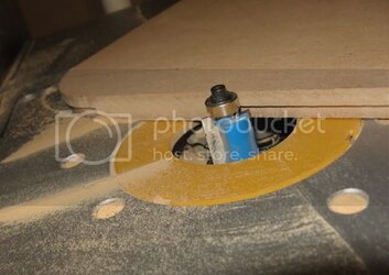
Using a flush trim router bit, the bearing rolls along the template on the top, the blades cut the bottom panel to exactly match.


.
 
Ahhh nice seeing a nice new mod work log! Looks promising, I like the design! You might be able to find some pneumatic push-rod cylinders from 'nerd kits' or even car trunk lids. Although the ones from car trunk lids might be a little over kill lol. I believe the SilverStone Raven case uses cylinders for its front door, maybe you can salvage some? or even buy them as replacements parts.
 
Okay, now its time to make my dado cuts into these panels. Once again, a dado is simply a sized groove.


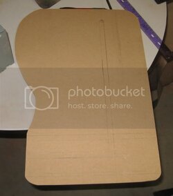
First I drew out what dadoes I needed:


Sidepaneldado1.jpg


There is going to be one vertical support which will also be the motherboard tray. Then there will be a horizontal support panel.


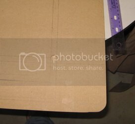
Next I used a forstner bit to mill out the starts of my dado cuts.

Sidepaneldado2.jpg


Then it was back to the router table. I used a straight 1/2" cutting bit. Then I adjusted my router table fence so that the router bit would fit in the exact hole I had milled out with the forstner bit as I mentioned above.

Then I turned the router on and milled out the dado groove in several passes. This is done completely blindly on the underside of the panel, so you have to draw some guidelines to make sure you stop at the right spot.


Sidepaneldado3.jpg


And here was the final product:


Sidepaneldadoed.jpg


Side panels with some dado grooves.


.
 
This looks so good. I'm planning on making a wooden case but it will not look as good as this or your other wooden case. Good luck!
 
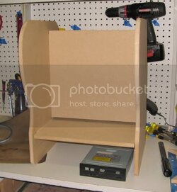
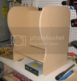
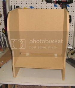
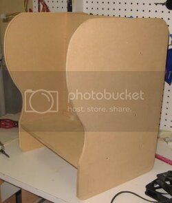
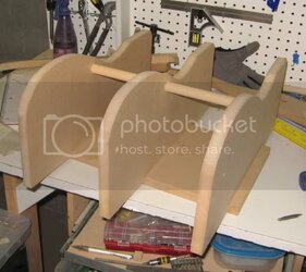
Cut the vertical and horizontal panels, slid them into the dado grooves, and put it together:


Firststructuralassembly2.jpg


Now we are starting to look like something!

Firststructuralassembly3.jpg
 
My next step was to cut a lip into the 2 vertical panels to inset the plastic faces.


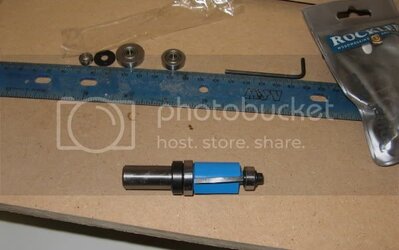
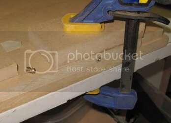
I’m going to introduce you to a pretty handy tool: adjustable trim router bit by Rockler.

Cuttinglip1.jpg

This is a straight cutting router bit with 2 replaceable bearing above and below the blade.


As I’ve currently have it set up, the bottom bearing is ¾” and so is flush to the blades. The top bearing is ½” in diameter, thus leaving a gap of 1/8” from the blade.

Put it into the router table, and adjust the height to where I want it.

Then feed the wood edge against the rotation of the blade, and thus I carved out a 1/8” deep (and ¼” wide) lip along the whole edge of the panel:

Cuttinglip2.jpg


I actually re-cut the vertical panels to something that fits better—then reassembled and here you go:

Afterlipcut1.jpg
 
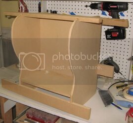
The next step is a bit of prep work. I made several squaring bars. These were simple strips of ¾” mdf, with dado slot grooved in at the exact same width of the case. I use these bars to make sure the case is square and not torsed or flexed. This is important because later when I bend the plastic, it really must be square.


Squaringblocks-1.jpg


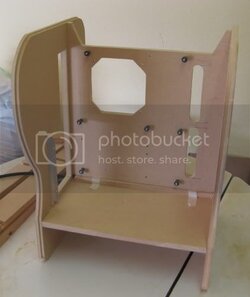
Once I know the whole case was square, I added brass inserts to the flat cross panels:

Brassinserts.jpg


And then with 4 screws in countersunk holes, the structure is now bolted together:

Structurebolted-1.jpg


In the future I will probably cover up these bolt holes with wood filler so that they will not be visible.


The next step made this project start really looking like a computer case: I shaped and cutout my panels.


Motherboardtrayshaping.jpg


The motherboard tray got its mounting holes, with 2 slots for cable pass throughs, and a under-cpu socket fan mount.

The slots were milled out with my router and a 7/8" straight bit. The under-cpu socket was milled out with the same jig I use for my benching stations.


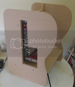
The pass through for the I/O panel and pci slots was also cut.

IOslotcut.jpg


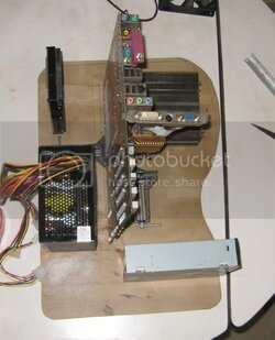
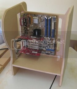
With a motherboard its looking pretty good:

Motherboardtrayshaping2.jpg

(I also made the pci slot mounting bracket).
 
My next goal was to form my curved plastic panels.

Starting with the fairly intricate front piece, which has a double curve.

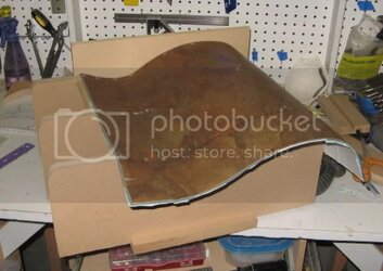
The first step was to create 3 identical baffles or ribs, each in the shape of the inner lip of the side panels, reduced again because they are going to get skinned with a surface sheet. I won’t belabor the construction of these—I used the same procedures with the trim router bit as above.

Baffles1.jpg


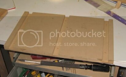
Next I created a base plate.

Bafflebaseplate.jpg


Put the 2 together and you’ve got the start of a form:

Formassembly2.jpg


Next I skinned the surface:

Formskinning1.jpg


Yes, those are 18” vinyl floor tiles, warmed to make them pliable, then screwed onto the ribs.


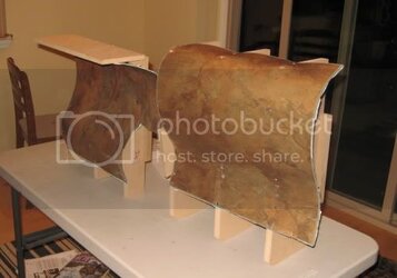
After some more repitious work, I also made a reciprocating form, so that I can sandwich the plastic in the form:


Plasticpressforms.jpg
 
Thanks,

I will be resuming this project shortly, now that I've finished moving across town.

navig
 
Navig,

What sources (stores) do you use for the illuminated fans & the 2.5" or 3.5" hdd cages ?

Also, do you make your plans available ? I'd like to try a hybrid of two of your designs, but I don't have your skill to plan the measurements & make the materials list.
 
Back