• Welcome to Overclockers Forums! Join us to reply in threads, receive reduced ads, and to customize your site experience!

FEATURED Building PWM Controller for 4 wires PWM fan

Overclockers is supported by our readers. When you click a link to make a purchase, we may earn a commission. Learn More.
I am going off of Bing's circuit on page 2. Is it okay/proper to use a TLC556 timer for the 2-98% controller instead of the NE556? I already have the TLC556 specs.

Also, the only connection I am unsure about is with the pot. What pins of the pot are connected to which connections?
 
I am going off of Bing's circuit on page 2. Is it okay/proper to use a TLC556 timer for the 2-98% controller instead of the NE556? I already have the TLC556 specs.

Also, the only connection I am unsure about is with the pot. What pins of the pot are connected to which connections?

TLC556 and NE556 are the same thing, just different manufactures, so you are good to go :burn:
 
Hello everyone :)

I've recently been lurking around this thread, going over the pwm controllers created by the members. I'm proud to say the 0-100% version I built works on my new Sanyo Denki 9SG1212G03 :)D), but it doesn't seem to work for my Delta TFC1212DEs. They simply run at full speed no matter what position the potentiometer is set to. To my knowledge there is nothing in particular different about the deltas, but I figured I'd ask you guys if there is anything I missed about them.

EDIT:

Solved the issue myself :). Turns out my fans are reverse PWM and the wires to the 4 pin socket connector were reversed- the tachometer wire was on the outside and was blue, while the PWM wire was on the inside and yellow -_-

Anyway, thanks for all the information you guys have posted on this thread for other budding FANatics :D
 
Last edited:
Hey everybody!

Planning on using the awesome circuit outlined on page 2 (the 0-100% version), hopefully scaling to a 4-channel fan controller with some other options and the ability to switch between motherboard control and manual control. Just had a quick question.

The schematic calls for the LM311 single voltage comparator, or equivalent. I don't have any of these lying around, but I do have a handfull of LM393N dual voltage comparators. These are basically just two single comparators in one package, similar to the 555/556 difference. Although the LM292N is still in the standard 8-pin package. My question is would this work for the circuit, using both comparators on the chip simultaneously for different fan control circuits. The only problem I could see would be crosstalk or something between the two units on the chip, I'm not familiar enough with that branch of electronics to know if this would be an issue. Worst I would do would be to use the ICs but only use one of the comparators, provided the specs are allowable.

I'll make a thread at some point showing how this project comes together, I've got some great ideas and am looking forward to getting going. Thanks for the feedback!


just like you said,
a dual comparator is just like a dual timers, or even dual op-amps.

I did substitute the 311 with the 393 in the past and it did okay, only tried for a single channel back then.
am planned to go for multiple channels as well, but I already happy with the 2-98% version.

you can always prototype on a breadboard and see how things going, though
 
I prefer the original recipes, though :chair:

F3NLHMHGNBEUTZZ.MEDIUM.jpg
 
Hey guys, this might be a bit random but does anyone know how to get a hold of / make a stand-alone PWM fan tachometer? Something with (4) 7 segment displays that just shows rpm?

Thanks,
 
Thank you for all this great information

Everyone has contributed so much to this thread and provided a great education for me! It seems like there are still some vestiges of life, so I'm hoping someone can spare a moment for a quick reply.

I started here: http://www.overclockers.com/pwm-fan-controller/ and then read through the majority of this thread. I think I now have the latest and best version of the circuit, but I'm confused about how the kickstart feature connects.

My specific application will attach cooling fans to furniture, so I'd like to power it from a DC adapter instead of a molex. I've included a couple small additions, like a voltage regulator for the 5V PWM circuit, a power switch, and a selector switch to adjust frequency. Please take a look at the modified version of your circuit diagrams if you have a minute. I'd really appreciate any advice you can give, especially letting me know how to hook in the kickstart circuit. Also, please excuse this terrible cut and paste job in paint.

Thanks for your help!

View attachment 171555
 
I delved into the thread around page 40 and learned a little more. Here's an updated figure with my tiny mechanical engineer's brain's best guesses:

View attachment 171636

-Not sure if jumping the two Reset terminals together is the right move, Bing's figure for the 0-100% circuit only show a 555.
-Same goes for wiring the 5V supply directly to VCC instead of leaving it on the same node at the Reset Terminals
-Still not sure the L7805 is a good way to run the PWM circuit off the same 12V power adapter as the fans.

I appreciate any help!
 
inVain, I am still waiting for you to make your rev. 89388-14b so I can finally buy one from you. You've come a long way since this thread started. I am jealous.

come on, there's nothing to be jealous of...
after all, you're the one who inspired us here :thup:

lately, I've been trying to rebuild what you built at the very first of this thread; the 2-98% with 555 instead of 556
intrigued with Arkade's finding about the cmos, so I used it as the buffer circuit.
it solved the whining issue on the 9sg :clap:

but sadly, the aluminum frame introduce quite unpleasant noise above 800rpm.
adding some dampening materials help reduce the noise (I used inner tire tube with cheap double foam tape).
it's quite funny how that cheap tape serves me better to dampen the noise rather than the 3M one :screwy:


speaking of jealousy,
this what it could bring after I saw what posted on #1937 :D
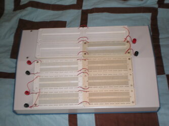
View attachment 172631

added an extra channel so I hope other jealous soul will pop in with better design :chair:
 
Hello experts, I am Bob from India. :)

This is one crazily amazing thread that I have come across, I mean so much of research on cooling fans is just amazing. :D

--------------------------------------------------------------------------------------------------------------

I have recently bought an Intel CPU fan to perform some experiments.

1. I want to run the fan at max RPM all time.
2. The fan will not be used inside a CPU cabinet.

My observation -

1. The fan has - Yellow(+ve), Black(-ve), Green(RPM), Blue(PWM input) wires.
2. The fan does not start instantly upon connecting to a 12V source. It gives 2 jerks & starts after 2 secs.
3. The PWM pin reads a 5.03V constant voltage all the time (I suppose its pulled up internally).
4. The fan is not running at max RPM for sure :(
5. When the fan starts, it touches high RPM and then settles down at a low RPM.
6. If I ground the PWM pin, the RPM drops further but fan keeps moving.

My attempts - I tried to supply a 5 volt using an IC LM7805 to the Green(PWM pin), but no use.
I also checked that the LM7805 is supplying 4.7 volts :(

Can any of the experts help me out ?
 
Last edited:
About controlling PWM fan, without any circuit, when you connect the PWM pin to the ground (negative), that is equal to 0% PWM duty cycle, the fan will slow down to it's rated minimum speed, and if you leave that PWM pin disconnected, it will automatically equal to 100% aka max speed, easy & nice isn't it ? ;)

Actually without any connection, that PWM pin is internally pulled high (electronic speak) equal to connecting to 5 Volt line (not the 12 volt), and remember, NEVER CONNECT THAT PWM PIN TO POSITIVE 12 VOLT, it will toast the fan's internal circuit instantly. :(


.

Hey Bing, This is not happening with the Intel CPU fan that I bought from Amazon. Will be sharing the pic by tomm.

Can you throw some light on this ?
 
Hello experts, I am Bob from India. :)

This is one crazily amazing thread that I have come across, I mean so much of research on cooling fans is just amazing. :D

--------------------------------------------------------------------------------------------------------------

I have recently bought an Intel CPU fan to perform some experiments.

1. I want to run the fan at max RPM all time.
2. The fan will not be used inside a CPU cabinet.

My observation -

1. The fan has - Yellow(+ve), Black(-ve), Blue(RPM), Green(PWM input) wires.
2. The fan does not start instantly upon connecting to a 12V source. It gives 2 jerks & starts after 2 secs.
3. The PWM pin reads a 5.03V constant voltage all the time (I suppose its pulled up internally).
4. The fan is not running at max RPM for sure :(
5. When the fan starts, it touches high RPM and then settles down at a low RPM.
6. If I ground the PWM pin, the RPM drops further but fan keeps moving.

My attempts - I tried to supply a 5 volt using an IC LM7805 to the Green(PWM pin), but no use.
I also checked that the LM7805 is supplying 4.7 volts :(

Can any of the experts help me out ?

that's strange.

wasn't the blue wire supposed to be the PWM line on a standard intel stock fan?
on every PC fan that I've dealt with, I just connect the power line to make them run at their full speed and omit the rest of the cables.
even when dealing with industrial fans, just by connecting their power lines will make the fans run at their full speed.

something match your description should be the "thermal controlled fan"; since they sense the ambient temps around to control their own speed
but they're typically come in 2 or 3 wire.

can't you get a friend's fan who upgraded to a 3rd party cooling? their stock fan should be lying around somewhere :D

it's quite typical for a 7805 to have some Vdrop, just make sure it powered by the same supply that's feeding the fan so you'll get a common ground.
if you happen to have an atx psu lying around, you can do the "jump start" and forget the 7805.

Thanks for your prompt response buddy. :)

I am attaching some clicks to clarify whether I am dealing with a correct fan type.

And I am sorry for the wrong info, I confused between the GREEN and BLUE wire while writing my post. Although, while experimenting, I was using the outermost pin(Blue wire) for PWM.View attachment 175964View attachment 175962View attachment 175965View attachment 175963


A clip showing the current readings and fan behaviour.

 
Last edited:
View attachment 175963


A clip showing the current readings and fan behaviour.


that clear things up
and that's what I would have done either if I want my fan to run at their full speed
I just connect that exact connection to whatever voltage that printed on the fan's label :thup:

I've been absent with the intel's stock fan for quite some times.
but after dealing with various amd's stock fans I found out that they came up with various speed.
some maxed around 3k rpms, while the others might went above 5k rpms.
you need to compare the appropriate data sheet and measure the actual rpm value of the fan
if the fan is still within 10% tolerance, it should be okay

about the jerking during the start up...
I had similar issue with a friend's PAPST, but in my case the fan might end up not spinning at all so I gave up on it.
I hate to say it, but I think it's a bad omen :chair:
I'd still keep it for non critical application, though :D

I never really measure the amps draw of my fans, but twice of the nominal printed value during startup is quite acceptable; at least by what people discussed so far on the forums.
here's a friend's video showing a power draw for the sanyo 9sg, rated @4A on 12v (48watt)
on the first few seconds, you can see the power consumption jump to 76watt+ during start up

aside from the jerking during startup, your fan looks ok to me
the power draw became stable after the fan's running.
you might wanna try to power up your power supply first, and then connect your fan to see if the jerks still occur.
 
Back