• Welcome to Overclockers Forums! Join us to reply in threads, receive reduced ads, and to customize your site experience!

FEATURED Building PWM Controller for 4 wires PWM fan

Overclockers is supported by our readers. When you click a link to make a purchase, we may earn a commission. Learn More.
mine shows the same result as yours :thup:

the 9SG is clearly a b!tch :D
too bad the vid of the troubled controller on post #88 was gone.
it shows how the controller was struggle without the additional chip when dealing with the 9SG, but it work okay with the xigmatek's fan.


a rough way to determine which line is the pwm can be done with connecting the "assumed" line to GND while the fan's spinning.
0v represent 0% duty cycle, while 5v represent 100%.
if the fan is throttle down /stop when the assumed line is grounded, then it is the pwm line.
this, of course; if the fan was expecting a non inverted signal.
for the inverted fans, 5v (100%) was needed to slow them down /stop them.

the common fan's signal requirement can be seen on this figure:
7622024314_f14c760b67_z.jpg

the method will not be valid for fans represented with the blue line,
this will require a fully functional controller.
 
Got it together, worked on first try. I just did the simple 2-98 first. Getting to all 5 of my fans to try them all at once isn't easy, I have to dissect all of them in a way I can return them if I'm not happy with this overall. Try that next. I do have a pretty big "step" in sped at one point in the pot's range. I may try to wire up that fine tune control and see how much adjustability that gives. What I really need to do it attempt to get this breadboard close enough that I can get the fan installed and see what the MB does when it says go one speed and the RPM sensor says it's going a different speed.

View attachment 182997

View attachment 182998
 
Since I am not intercepting the whole fan header and only the PWM line, and even if I was, 5VDC is going to be harder to source in the server chassis. There are no molex connections, ther eis one tiny header for a optical drive and I've already used that to connect a SSD boot drive. Wary of connecting this circuit to that header right beside the SSD. But that's about my only option for 5VDC. Short of adding a little LM7805 5V voltage regulator like I did on my breadboard. But I really don't have room for it, either.

I read in the fans datasheet the PWM pulse could be more than 12V (if I read it right). Can this circuit run off the +12VDC rail for + instead of 5VDC? Or does that throw all it's component values off? Blow the 555, kill the fan, etc. I have access to 12VDC at the fan header.

EDIT: Nevermind, I found the answer in the thread. Bing said is was OK FOR A FAN WITH 12V RATED PWM, just be sure the caps voltage was OK. But now I'm chicken because the wiring diagram on the datasheet was wrong, maybe the PWN spec is too. Don't want to blow a fan. Will look into adding a 7805 VR. In my breadboard setup I was using without any filtering caps. Still worked... I've used them plenty of times in less critical things, never had an issue. Well that I could "see" anyway cause I don't have a scope. Don't know how big a deal that is.
 
Last edited:
congratz :)

What I really need to do it attempt to get this breadboard close enough that I can get the fan installed and see what the MB does when it says go one speed and the RPM sensor says it's going a different speed.

I'm quite curious about this as well, did you manage to tried it yet?

the 556 can handle up to 18v (at least that's what the datasheet says).
but I'd be more comfortable with 5v supply, it'll be greatly improve the controller compatibility with other fans which only allow 5v for the PWM line.
I'm also concerning about the drift on the output frequency with the 12v supply.

I like the 7805 solution better,
if you manage to place the controller somewhere inside the case, you should manage to add this regulator as well.
they are also available in smaller package; such as the TO-92 or SOIC-8 ;)
 
I'll keep you posted. I have to integrate it into this contraption, which is removable complicating things. You can see one PWM line I've pulled out. Plan to do the others similarly. Further complicating this, I have to be able to return the server. If I'm not happy with this it's going back, so all my fan wiring has to be non-destructive. I've got 2 weeks to decide (RMA issued good for 2 weeks). I still may punt and just build a server but that's a topic for a different thread.

I'm gonna stick with a VR and run the controller with 5V I decided. With or without filtering caps. I remembered the header (the only header on the whole MB) where I attach power to the SSD, I'm not using that 12V line as teh SSD only used the 5V line. So I'll either pull power from there, or intercept 12V off the middle fan header. Middle fan header is better because then the whole assembly is still un-pluggable, but mechanically it's much more difficult. Electronically probably better because I'm closer to the same ground the fans are using.

I had a small board I made years ago for something unrelated to hold a bank of diodes. I used that to cobble together a PCB for the single 556 controller (which I hope can do all 5 high-resistance fans). Maybe only one step up from the bug style. You can see there's no place to put a TO-220 7805. I didn't think about their smaller form factors. Alas, no way to get one of those here cheap due to shipping, or quick for the same reason, so I'll trudge on and stick the big one to something with tape in line somewhere, ghetto style :)

For searches sake this is a Dell R710 Fan Bank

View attachment 183010View attachment 183011
 
Last edited:
Look what I found in my old spare parts. A couple of TO18 5v VR's, and the matching tantulum caps. Now that little board is really crowded LOL. Except for the POT, I'll have to forgo spiffy headers and make direct wire connections for the power and signal now...

View attachment 183012
 
I like the PCB :thup:
did you apply the solder layer by yourself, or did it came as a HASL finish?

you should be able to mount the TO-220 on either side of the board, just drill a 3mm hole and secure it with a bolt and nut or some spacers would be better.
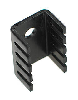
or mabye attach this kind of heatsink, as it shouldn't look much wider than the TO-220 itself:
TO220S.jpg

and the fans, two look differ than the other.
the middle PFC have different P/N number than the other, did it came with the rest of the fan?

for this kind of setup, I think I'll gang them up via the same controller as well.
hope everything runs smooth :beer:


edit:
glad to see you shorted out that VR problem :thup:
 
did you apply the solder layer by yourself, or did it came as a HASL finish?
Don't know what HASL is but this was a PCB I had made as a proto-board form PCBexpress several years ago. That's the way they come. Traces, through-holes plated, but that's it. No soldermask or silkscreen. FR4 and tinned traces only. Very handy service, cheap enough, and they give the software away.

I got the little PCB all soldered up. Had one issue where once it was adjusted full speed the rpm would not come back down. Found I missed grounding the VR. Fixed that and the PCB worked as desired on a single fan. Hardwired the 12V in (red), ground (green), and PWM (blue wire). The 3-pin header goes to the POT.

View attachment 183026

Next was to do the mechanicals to get it integrated to the removable fan bank. I couldn't believe my luck. I removed a little plastic blank covering a cavity between to fans. My PCB fit, perfectly (snug enough to hold but not bind) into the cavity at an angle. No screws, no standoffs needed. What luck.

View attachment 183028

View attachment 183027

Using a couple of terminal blocks stuck to the side with VHB tape, found a way to intercept the 12VDC and Ground from the middle fan (only), and also used the same thing to connect the 5 PWM wires to each fan:

View attachment 183029

View attachment 183030


Here's the (temporary) wiring with the fan assembly laying on its side, and then plugged into the chassis:

View attachment 183031

View attachment 183032

The controller ran all 5 fans properly. I can adjust them as low as they will go and they still startup without the booster circuit. As for control they actually work better wiht all 5 connected for some reason. Response to the POT has much less delay vs controlling one fan.

The fanspeed program misreports Fan #1 (which is not the different one). Whats odd is the Dell utility reports all 5 fans rpm, but it's a web interface that has to be refreshed. the fanspeed program refreshes on it's own so I used it. No idea what the various temp sensors actually go to. The Dell utility only shows the boards ambient temp, and I'm not sure what that means really. Figured I'd watch the fanspeed sensors and see if any changed hotter vs running the fans faster. If anyone knows of another program to monitor temps and fan speeds let me know please.

View attachment 183033

So thanks to all the very helpful folks who contributed to this thread I have a working 5 fan controller built into a Dell R710 Server. My only worry now is should the fans actually need to speed up, I've overridden that BIOS control. That said, it's just a file server, does nothing else (right now) so its load shouldn't change much, I don't think.

All that's left is to make a L bracket for the POT so I can get to it from the front. I will put it behind the grill so it takes a screwdriver to adjust it. That way no one can accidentally bump it and turn the fans down.

And...oh yeah. I don't seem to be getting any hardware errors from the Dell box even though the fans aren't running as fast is it told them to run. Well, it' snot on the front panel anyway. So at least that's good...

Special thanks to inVain for watching over my shoulder and the tips.
 
Last edited:
you're welcome, getgray :)
glad to hear everything works as expected :thup:

I really like those pics you've uploaded,
they bring back memories of the old forum I used to know ;)

HASL = hot air solder layer
it's a good practice to prevent oxidation on a PCB when it'll be stored for a long periods of time


whenever I run all my fans through a controller,
I usually run a software load test (intel burn test) to figured out what the maximum temperature I would be expecting during heavy loads.
since this software running unnecessary heavy (100% cpu load), I can expect for lower temps during my daily activities on the system.
as for the s/w monitoring, I really like the "h/w monitor", and recently I found "open h/w monitor"; these software keep the logs for minimum and maximum temps reached, it's also get refreshed quite often.
I never had any chance to try out these software on a server environment, but I hope you can get some alternatives to do it.

again, thanks for those lovely pics :thup:
 
re pics, welcome.. I wanted to post somewhere for others who may try the same thing. I got this server off eBay. Clearly came from a clean environment because it is like new, not so much as a speck of dust inside. Dual XEON L5520 CPU's, 32Gb RAM, (8) hotswappable 6Gps 75G SAS 15k hard drives in caddies, with built in HW raid, in original packaging, for $150 USD !!. It's a LOT of PC for $150. When I looked for a solution to the fan's, I could see others had tried, too but there just was no way (found) to override the fan speeds. Till now. :)

What I'd really like to do is program a PIC to read the incoming PWM signal, read an attached POT, and depending on the POT setting shift the incoming PWM duty cycle down by a proportional amount, then output the revised PWM signal. That way if the BIOS ramps the fans up, the fan controller ramps them up, too, just not as fast as Dell thought they should go. A project for another day (month LOL)

Re CPU loading, I was right in line with you. Of all of them I tried (speedfan, HW monitor, open HW monitor) the only ones that "see" my fans are speedfan and the built in Dell OpenManage tool. And speedfan gets one of them wrong oddly enough. All of them read the core temps on the CPU, but only speedfan shows other sensors, of which I have no idea what are. I disconnected both RAID cards to be sure that one speedfan was reporting as hot wasn't one of them, I didn't see a sensor come or go. Both raid cards have heatsinks and the added one gets pretty hot. That's the one that worries me, as that's the gateway to the precious data in (2) attached RAID arrays. One of those at is RAID5 9TB, the other RAID 10 (mirrored and striped) 1TB of VERY important to me data (photos). That was the cause of all of this after all, adding that card is what made the fans go up. I'll probably find a way to add a smaller, much quieter fan near that RAID card later.

Anyway, for load testing I used a program called "OCCT" which included 100% CPU and 100% memory usage test. I let both tests run for about 5 minutes till the temps seemed to peak and plateau. I got up to about 57degC on some of the 8 cores (some were less). I understand that under 60degC (open to correction here) was fine for these CPU's? Both "packages" shows 60w which is exactly what Intel's specs say these 2 CPUs are, so that's good to know. I was hoping these weren't power hungry 80w+ CPUs, happy to see some sort of verification FWIW.

Those temps were with the fans running a reasonable ~4000ish rpm, even a little lower than original w/o the extra RAID card (~4500). I can't imagine anything the server will do to hit 100% at a peak, much less sustained. I may even disable or pull a CPU just to see how it does. Wanting to keep the server as low power as I can.

P.S. final note for anyone following this. I did use the CMOS version of the 556 chip, and I used the original single 556 2-98% design that I put in my first post a page or so back. I did not need the startup booster circuitry, nor did I need the secondary 556 chip. KISS.

Cheers,
Scott
 
Last edited:
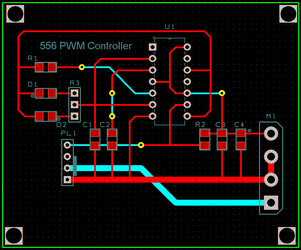
556 with SMT parts.
556PCB2.jpg

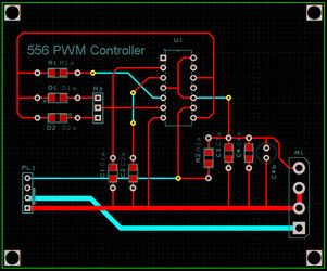
556 SMT and through hole combo
556TH.jpg

The SMT parts have the "a" in the ref number, C4 is for through hole ceramic cap (yes they make 10uf ceramic caps), C4b is for electrolytic cap.
All I need to do now is have the PCB made.
 
Last edited:
Hello every1! how you doing?
have been reading this thread for a few days now, very interesting!
i was wondering, will this sort of circuit be able to control 10 PWM Noctua fans (Max. Input Power//Operating Voltage 1.56 W/12V, Max. Input Current 0,13 A. i guess this info not much related to PWM signal itself)? http://noctua.at/en/products/fan/nf-a14-pwm/specification
was a bit of a puzzle to figure out everything and put it all together lol :comp:
thanks in advance! i'll have questions about parts later, if some1 is still around )))


View attachment 187690
 
Don't know what HASL is but this was a PCB I had made as a proto-board form PCBexpress several years ago. That's the way they come. Traces, through-holes plated, but that's it. No soldermask or silkscreen. FR4 and tinned traces only. Very handy service, cheap enough, and they give the software away.
View attachment 183026

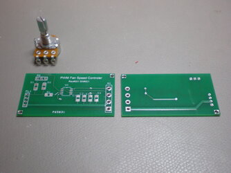
I had these made at Advanced Circuits.
DSCN0595.JPG
 
Hi All, I'm a noob. Have some questions. Will Bing circuit 0% to 100% be able to control a 48vdc AVC 4 wire fan? If so any modifications to be done to the circuit.

Regards

Johan
 
I'm struggling to wrap my head around this. Would it be possible to use this (they call it a 12-40v PWM controller) to control a PFC1212DE via the PWM pin?

I can't work out how you would wire it up. The controller has four pins; power -, power +, motor +, motor -
 
Back