- Joined
- Nov 11, 2007
So im looking to mod a 80gig Intel X-25MG2. Just wanna see if i can do it.
Back story i work at a electronics manufacture so i got access to expensive tools and components at dirt cheap prices.
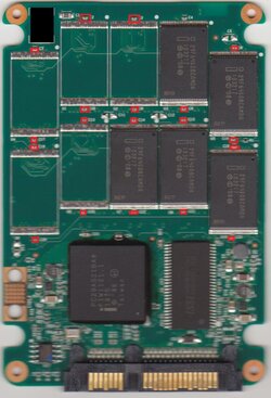
To my understanding the X-25M's all have the same pcb. Only the 40gig uses 5ic's 80 uses 10ic's and the 160 uses 20ics. The IC locations are numbered on the pcb so this is what i was wondering. We had some spare ic's same as those used on the X25-M's 8gig chips, I checked. So i got a spare 80gig X25MG2 i don't use any more and i was thinking about trying to see if i can turn the 80gig into a 128gig. So i got a question.
Do the X25-M's all share the same firmware? If so does anyone know if its just 40,80 and 160? If it wont support 160 im going to try and order 5 more from the supplier Monday and go all out but i would like to test it with whats on hand,
Anywho if anyone can shed some light in on this i'll start the project soon and post some pics benches before and after as well as some part numbers and tips on how to do this. Its pretty simple but i'll be using the SMT heater to flow the ic's and not a soldering iron. "Faster and i can just set it in and wait for it to come out.
Update.
IC's are soldered on all looks well and should work. Flashing the firmware later this week and testing. This is the 40-80gb mod first.
Update. Pic to show you what a 40gb model looks like. 5 more ic's to fill this side makes this the 80gb and the 160gb required a total of 15ic's 5 to finish the top and 10 for the back. Note the red boxes. These are a part you want to be very careful by when modding as you might hit it and unsolder it.
Tip is to get some solder on the legs of the ic's and being very careful and not letting the iron sit on them to long remove the excess solder. Then use some good flux and line the ics up. this is the part that takes the most time and im working on a way to help speed the inspections process up "see bottom of the post" I used some silicone adhesive on the bottom of the ic's and after lining them up i let them sit for 6 hours to cure. After cured just use a fine tip on a soldering iron and tack each pin down. Then inspect each solder join. You dont need to put any solder on the pad, just flux them as they have solder on them from when they were produced or you would see the gold on the pads to protect them from corrosion.
To help speed things up if anyone else does this i'll making a ghetto style AOI. Basically you dl a template im doing to make then scan your ssd and when your image is sized right for the template you would only see green if you see silver then you have a bridge and will need to unbridged it.
I'll get a better scan of it. Looks like i have to prop the top of the ssd to the same height as the sata connection to keep it all in focus. I'll also get a scan of the modded drive but please note mine will look better than yours because i special equipment at my working for doing this. You can do it by hand but it takes a little longer and wont look as good.
Back story i work at a electronics manufacture so i got access to expensive tools and components at dirt cheap prices.
To my understanding the X-25M's all have the same pcb. Only the 40gig uses 5ic's 80 uses 10ic's and the 160 uses 20ics. The IC locations are numbered on the pcb so this is what i was wondering. We had some spare ic's same as those used on the X25-M's 8gig chips, I checked. So i got a spare 80gig X25MG2 i don't use any more and i was thinking about trying to see if i can turn the 80gig into a 128gig. So i got a question.
Do the X25-M's all share the same firmware? If so does anyone know if its just 40,80 and 160? If it wont support 160 im going to try and order 5 more from the supplier Monday and go all out but i would like to test it with whats on hand,
Anywho if anyone can shed some light in on this i'll start the project soon and post some pics benches before and after as well as some part numbers and tips on how to do this. Its pretty simple but i'll be using the SMT heater to flow the ic's and not a soldering iron. "Faster and i can just set it in and wait for it to come out.
Update.
IC's are soldered on all looks well and should work. Flashing the firmware later this week and testing. This is the 40-80gb mod first.
Update. Pic to show you what a 40gb model looks like. 5 more ic's to fill this side makes this the 80gb and the 160gb required a total of 15ic's 5 to finish the top and 10 for the back. Note the red boxes. These are a part you want to be very careful by when modding as you might hit it and unsolder it.
Tip is to get some solder on the legs of the ic's and being very careful and not letting the iron sit on them to long remove the excess solder. Then use some good flux and line the ics up. this is the part that takes the most time and im working on a way to help speed the inspections process up "see bottom of the post" I used some silicone adhesive on the bottom of the ic's and after lining them up i let them sit for 6 hours to cure. After cured just use a fine tip on a soldering iron and tack each pin down. Then inspect each solder join. You dont need to put any solder on the pad, just flux them as they have solder on them from when they were produced or you would see the gold on the pads to protect them from corrosion.
To help speed things up if anyone else does this i'll making a ghetto style AOI. Basically you dl a template im doing to make then scan your ssd and when your image is sized right for the template you would only see green if you see silver then you have a bridge and will need to unbridged it.
I'll get a better scan of it. Looks like i have to prop the top of the ssd to the same height as the sata connection to keep it all in focus. I'll also get a scan of the modded drive but please note mine will look better than yours because i special equipment at my working for doing this. You can do it by hand but it takes a little longer and wont look as good.
Attachments
Last edited:


 Pics please !