• Welcome to Overclockers Forums! Join us to reply in threads, receive reduced ads, and to customize your site experience!

delta afc1212de pinout

Overclockers is supported by our readers. When you click a link to make a purchase, we may earn a commission. Learn More.

psionic98

Member
Joined
Jun 22, 2009
Does anyone have the pinout for a fan header for this PWN fan? I can't get a good closeup of the connector to know what to hook up.. I have an old pwn that bit the dust thus giving itself to be sliced up to work for the better good of the delta!

I know the positive/negative since I did test it and it works (what a screamer.. i love it)

EDIT: might have a hit from tomshardware tomshardware

EDIT2: found a great article at overclock.net on it.. problem solved!
 
Last edited:
lol 8 minutes between post and resolution...and no one even had to say anything :D

EDIT:mad:jmtyra, that's my backup site, i like allpinouts.org cause of their format and extra info
 
Red and black are your 12v and ground, respectively, blue is RPM monitoring, and yellow or white is going to be the PWM wire. I can see how it can throw you off, knowing that Yates have a yellow wire for RPM monitoring. I know there are a few others that change things around a bit too. I have seen some that used white wires for RPM monitoring too.

Hope this helps.:thup:
 
I've always seen yellow for RPM and blue for PWM...I'd really like to see the pinout on this thing if someone has a link
 
hah, yea, but it's not specific to the fan (which may or may not have the pwm and rpm coloring reversed...which is odd because delta is usually pretty strict to industry standards
 
lol, I've got some friends who run servers (professionally) and from what I hear from them, I wouldn't be surprised if they got soldered back on to the wrong pads...possibly intentionally lol
 
Ahhh, ya you got me there -- there isn't a standard as I understand it...but as long as the wires match? :shrug:

Mmm...maybe you could run a DMM to it, and see which one had varying resistance (or whatever the change would be with a PMW wire)? Just thinking out loud...

:)
 
pwm is an input signal, you could just see which had output, since the rpm wire would be outputting some sort of signal...you might need a scope for that though, depending on how the RPM wire works.
 
OH! I'm so stupid...you could just see what wire is left after applying the +12 DC to the other wires. Why didn't I think of that earlier??
 
yea, if you can get at the circuitry it's easy, but you can't do that on all fans.
 
Yeah sorry about that.. I originally was going to post the question and then head to bed since it was midnight, but then decided to screw the time and look around some. And deadly is right.. these were Dell server pulls in which they changed around the wires and pinouts for their special adapters..

Thanks for the site links too.. all bookmarked!
 
With PWM fans, you can always check for the PWM controller wire by going to the ground wire with the rpm and PWM sense wires and see which controls speed. Going to ground with the rpm wire shouldn't hurt the rpm sensor and going to ground with the PWM wire should bring the motor down to it's minimum speed.
 
Thats good info to know.. I found an article on overclock.net that shows this exact fan from a dell pull and how the wires are switched around and stuff. Now I just need to sacrifice my old cpu hsf fan connector for this bad boy!
 
Thats good info to know.. I found an article on overclock.net that shows this exact fan from a dell pull and how the wires are switched around and stuff. Now I just need to sacrifice my old cpu hsf fan connector for this bad boy!

not really, you can order new ones for super cheap
 
This is an old thread, but just in case anyone googles this question and gets this page.
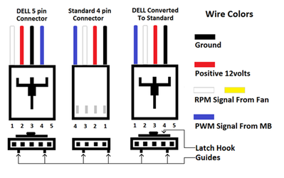
The picture below shows how to convert dell to a standard fan plug and use the Dell connector. They are very easy to convert using the existing plug; use a razor blade to push the lock down and pull the pins, then fix the lock and reinsert the pins into the correct positions. The latch on the Dell plug and the 5th pin hole can be shaved off to make it look like a standard 4 pin plug, or you can leave it in like it is so you can convert it back anytime you need a Dell fan.

Dell fan plug.png

Some of these fans are bad to the bone, and well worth the effort to convert.
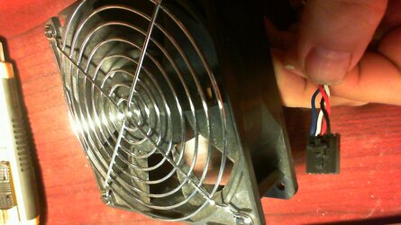
The one below is 38 x 120 mm, 1.3 amp, 130 CFM, PWM controlled.

2014-10-04 22-05-59.537.jpg
 
Last edited:
This is an old thread, but just in case anyone googles this question and gets this page.
The picture below shows how to convert dell to a standard fan plug and use the Dell connector. They are very easy to convert using the existing plug; use a razor blade to push the lock down and pull the pins, then fix the lock and reinsert the pins into the correct positions. The latch on the Dell plug and the 5th pin hole can be shaved off to make it look like a standard 4 pin plug, or you can leave it in like it is so you can convert it back anytime you need a Dell fan.

View attachment 154598

Some of these fans are bad to the bone, and well worth the effort to convert.
The one below is 38 x 120 mm, 1.3 amp, 130 CFM, PWM controlled.

View attachment 154599

Just bear in mind that not all Dell Delta fans are the same PWM setup. There are a handful out there that have the appropriately colored wires, but arent PWM, or arent standard PWM. I have 2 AFB1212s from a Dell T5400 used as a hard drive cooling fan and they did not work through PWM control at least through the motherboard's output. They may have been a different voltage or reverse PWM, I dont know.
 
Back