-
Welcome to Overclockers Forums! Join us to reply in threads, receive reduced ads, and to customize your site experience!
You are using an out of date browser. It may not display this or other websites correctly.
You should upgrade or use an alternative browser.
You should upgrade or use an alternative browser.
DIY Fan Controller for PWM Fans
- Thread starter Overclockers.com
- Start date
- Joined
- Dec 6, 2010
I can't believe I never posted in this thread!
I'll be PMing you later today.
You might want to make a classified section thread for them if you're going to send them out. I've seen the mods go both ways on that sort of thing.
Oh I'll post over there
- Joined
- Dec 6, 2010
- Joined
- Dec 6, 2010
Awesome! My 555 boards shipped my direction today, should get here friday or so. I'll post pictures
Looking forward to seeing it.
- Joined
- May 10, 2009
Gotta learn SMD somehow. SOIC-8 and 0805 are good learning bits.
I made mine SMD for just that reason, I'm going to see if I can sell a couple as "Learn SMD and build something useful" kits.
They're also useful in that they can be run at 12V for switching MOSFETs if you don't want to control fans.
I made mine SMD for just that reason, I'm going to see if I can sell a couple as "Learn SMD and build something useful" kits.
They're also useful in that they can be run at 12V for switching MOSFETs if you don't want to control fans.
- Joined
- Dec 6, 2010
Gotta learn SMD somehow. SOIC-8 and 0805 are good learning bits.
I made mine SMD for just that reason, I'm going to see if I can sell a couple as "Learn SMD and build something useful" kits.
They're also useful in that they can be run at 12V for switching MOSFETs if you don't want to control fans.
Use 1206 to start with, 805 is small
- Joined
- Dec 6, 2010
I thought about putting those on the 555 thing, but they're so big I could have done through-hole at that point
I Did It Wrong and started with 0402. Those things are a pain.


 There are some parts so small, if you drop them on the floor, don't bother looking for them
 - Joined
- May 10, 2009
Yeah those are the ones.
Forget the floor, if you drop them on a wood table you probably won't ever find them. You need a solid color very flat surface to find the damn things.
I've stopped using them except when I have to, moved up to the much nicer 0603 and 0805 sizes
0402 is a lovely size for 0.1µF decoupling caps though, you can plop 'em between 0.1" power/gnd pins and they have essentially zero trace length!
- Joined
- Dec 6, 2010
Maybe design the board to be able to use either through hole or SMD? I sometimes see that approach on production hardware and whether they use SMD or through hole depends on component availability.
Yep, great for manufacturing, but a pain from a design stand point, you have to find room for all the through and SMT parts in a small board.
- Joined
- May 10, 2009
As soon as the parts get here, these will be in the classies as kits for learning SMD and building a fan controller!


Definitely will still be cheaper to build your own, as you don't have to pay for my time packing things up, collecting parts, part shipping to me, etc.
The kits should be pretty cheap though.
Let this, and Whitehawk's boards, be an inspiration to people who want to make their own boards! I haven't had any formal training in this at all, you can learn it too
The trick to 0805 soldering is, get good tweezers.
Then you put solder on one pad, let it cool, get the part lined up with its pads but slid over enough that it is resting flat on the surface of the PCB, not on the little solder mound. Hold it with the tweezers, melt the solder and slide the part into it. Let the solder cool, then solder the other end.
That goes for SMD chips, too. Do it with one pin, get the other pads aligned before you solder more than one pin, then you're home free.
- Joined
- Dec 6, 2010
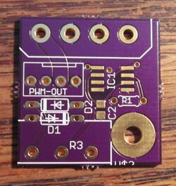
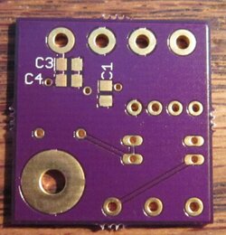
As soon as the parts get here, these will be in the classies as kits for learning SMD and building a fan controller!
View attachment 145434
View attachment 145435
Definitely will still be cheaper to build your own, as you don't have to pay for my time packing things up, collecting parts, part shipping to me, etc.
The kits should be pretty cheap though.
Let this, and Whitehawk's boards, be an inspiration to people who want to make their own boards! I haven't had any formal training in this at all, you can learn it too
The trick to 0805 soldering is, get good tweezers.
Then you put solder on one pad, let it cool, get the part lined up with its pads but slid over enough that it is resting flat on the surface of the PCB, not on the little solder mound. Hold it with the tweezers, melt the solder and slide the part into it. Let the solder cool, then solder the other end.
That goes for SMD chips, too. Do it with one pin, get the other pads aligned before you solder more than one pin, then you're home free.
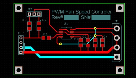
umm where is R2?

- Joined
- Dec 6, 2010
That's one of the great mysteries of life.
I was wondering about that too, I have no idea. I think I must have plopped two through hole resistors down and then the pot, then realized I only needed one resistor.
I also noticed that pin 7 is not connected to gnd that I can see, will it work with out that pin connected to gnd?
- Joined
- Dec 6, 2010
Hmm, totally missed that. Looking at the 555 schematic it should still work. I'll have to breadboard it to make sure.
If it don't work, after you solder the IC, you could use a piece of 30 gauge wire and connect pin 7 to the GND side of C2.
Similar threads
- Replies
- 0
- Views
- 698
- Replies
- 49
- Views
- 4K
- Replies
- 2
- Views
- 412
