• Welcome to Overclockers Forums! Join us to reply in threads, receive reduced ads, and to customize your site experience!

DIY Fan Controller for PWM Fans

Overclockers is supported by our readers. When you click a link to make a purchase, we may earn a commission. Learn More.
This got started way back in the 1800's when batteries were fist made, people thought that current went from + to -, when vacuum tubes came about, they found out that it went from - to +, but some people did not want to change their way of thinking, so we now have Conventional current flow (+ to -) and Real current flow (- to +).

Blame Ben Franklin...while electrons flow from - to +, Ben created the "standard" that current flows from + to -. Electrons flow the "opposite" way through a diode, but by "standard" current flow, it goes in the direction of the arrow on the diode...anode (+) to cathode (-).

Also, the electrolytic cap will not filter out all of the noise by itself (it doesn't look like a cap at higher frequencies). You usually put a 10 uF and 0.1 uF in parallel...the 10 uF for low frequency droops, and the 0.1 uF for high frequency noise.

Also, if you are having noise problems, try twisting the power supply input wires to get as many turns per inch as you can (I used a drill in the old days). This will help cancel out noise from the power supply to and from the circuit.
 
:rofl: There are 3 rules to breadboarding, 1. Check connections, 2. Check connections, 3. Check connections :rofl::chair:

- - - Updated - - -

Trim the wires and component leads so they don't get bent down and short on something else.


p.s. Go back 2 pages and look at my board :rofl:

It's a good idea to ask a company to build a pcb for you, but I don't know any in my country :/
Now that the circuit is working, the only question I have in my mind is: How can I flip the work of the potmeter, so it increasing to the right?
Thanks in advance :)
 
Last edited:
It's a good idea to ask a company to build a pcb for you, but I don't know any in my country :/
Now that the circuit is working, the only question I have in my mind is: How can I flip the work of the potmeter, so it increasing to the right?
Thanks in advance :)

you can flip the two diodes direction,
or simply flip your pot connection
 
Hi, I've ordered all the required parts to create the multi-fan PWM signal generator using the 556 IC. I'm actually modifying an entertainment center to have variable speed cooling fans for a console replacement/HTPC ITX build. I'd like the fan array to run off of a 12V power power adapter plugged into the wall instead of a molex from the PC. My question is, can I use an L7805 5V regulator to step the voltage down for the PWM circuit running in parallel with the 12V fans. Would there be any issue tying everything back into the common/ground on the 12V wall adapter?

Thanks for your help!

Edit: My latest post in the original thread contains more specific questions and a circuit diagram made with MS Paint!
http://www.overclockers.com/forums/...ng-PWM-Controller-for-4-wires-PWM-fan/page108
Search for "common ground" in my recent posts.

--
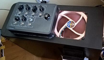
I got so carried away by the fact that my entire controller works (except for that one PWM fan) that I forgot to post the final version of it! Here it is!

1 through 4 are pot-controlled, P1 through P3 are PWM-controlled. The big knob on the right is for RPM readout selection (from which fan the PC reads the RPM signal). Enclosure from an old modem-router, vector graphics done in Inkscape, printed out on a regular office paper and laminated :)
 

Attachments

  • WP_20160116_12_13_08_Pro_ed.jpg
    WP_20160116_12_13_08_Pro_ed.jpg
    135.2 KB · Views: 367
I'm using 4 San Ace 40mm x 40mm x 56mm counter-rotating fans that I pulled from an old server. My fans are each 12V, 1.2A and are powered by a 12V, 8.3A power supply. The fans are running in parallel.

I set up this circuit using the dual 555 timer setup. It is powered by a 5V, 0.5A USB power supply. In theory, the only difference between my circuit and the one shown is the the 680pf capacitor. I used a .01 uf capacitor because I could not find the 680uf at my store and didn't feel like paying shipping for one component.

The setup works great when I have the PWM signal going out to a single fan. With the potentiometer dial all the way to one side, I can get full RPMs. With the dial all the way to the other side, I can get very low RPMs.

When I add a fan in parallel, I can run both fans at full RPMs with the dial turned all the way to one side, but the fans cut out before I'm able to turn the dial even half-way towards the other side. In other words, with two fans in parallel, I am not able to use the full range of the potentiometer without the fans stopping. I also noticed that the the further I turn the potentiometer's dial away from full RPMs, the less constant the RPMs of the fans seem to be. There is a consistent audible change in fan pitch.

My best guess is that I (1) screwed up the circuit is some minor way, (2) don't have enough current for the PWM (which seems very unlikely), (3) grounded the PWM circuit incorrectly, or (4) I am not truly in parallel like I thought.

Does anyone have any ideas?

EDIT: Perhaps the PWM signal is degrading too much when connected to two fans. This is strange to me given that the connections are in parallel.
 
Last edited:
Try connecting the fans directly to the output of the 555?

I played around with the C2 capacitor value a little bit and noticed that my fans had a wider range with lower values. I ended up using a 100pF capacitor instead of a 680pF or even a 470pF. It must have something to do with frequency and the number of fans that I have. Who knows.
 
It's a good idea to ask a company to build a pcb for you, but I don't know any in my country :/
Now that the circuit is working, the only question I have in my mind is: How can I flip the work of the potmeter, so it increasing to the right?
Thanks in advance :)


Zot Engineering in Scotland build my surface mount stuff on pick and place assembly machines that test the components as they are assembled and also use vapour phase reflow for soldering, pretty cool, Both In the sense that it is nifty and very precisely temperature limited by the phase change of the liquid medium used in the reflow oven. Your components don't get cooked, reduced thermal shock blah blah etc....
If you give them a bill of materials they source all your components for you aswell as using their buying power in China to get a favourable price.

They make Printed circuits for you too.

The best thing is that they do low volume work so you can prototype stuff without committing to a big batch.
I'm not sure what kind of volume you were thinking but making ten circuits costs about the same as making 500, you just do more panels.........

The Sheetmetal Division can make you enclosures or a bit of bent metal for a drive bay if you want.

Its kind of a one stop shop for this kind of low volume work.


http://www.zot.co.uk/

I'm very interested in getting hold of some cheap and reliable PWM controllers for high amp (3-5 amp)fans. The market is there its just not big enough for Corsair or whoever to bother with. Why do think you find so many little threads all over the internet that talk about 555 timers and DIYing TRUE PWM controllers, not the crappy low amp per channel fake PWM over 3 pins people are trying to flog you all over the place.

I suppose it might be fun to get together and do a refined design and sell a few, see how it flies?

Anyone up for it?
lol.
:)


Hmmmm, Britain is leaving the EU.......
 
Last edited:
Hey all,

Long time lurker around here, but first time poster.

This is a great guide, and while I am no stranger to the soldering iron, my knowledge of circuits is somewhat limited.

Could anyone explain to me in layman's terms the difference in end results from using the single 555 design vs going for the 556 (dual 555) design?

Essentially, all I need is to be able to control the duty cycle for a single wire, I intend to attach to pin 4 on a PWM fan splitter, preferably from 0% all the way up to 100%.

Also, jeez, the strips on the strip board seem awfully small. How on earth do you avoid shorting them together when soldering?

Much obliged,
Matt
 
Last edited:
Well, this thread appears to be mostly dead, but I figured I'd post my follow-up anyway.

I finished my 556 based circuit but something is wrong.

I have double and triple verified that my connections match the diagram, and double, and triple checked for any shorts anywhere.

My behavior is that with the pot turned all the way counter-clockwise, the fan is at minimum speed. Turn the pot clockwise and nothing happens until the pot maxes out, at which point the fan suddenly switches to maximum speed. From this point if I turn the pot counter-clockwise again the fan stays at maximum speed all the way until I reach the minimum setting, at which point the fan switches to its minimum speed again.

I noticed that I didn't wind up with exactly the same components as the op. my 680pf - when I received my order - wound up not being a ceramic disc capacitor but rather was electrolytic, and thus polarized. I soldered it such that the negative pole was on the ground side, and figured it wouldn't make a difference, but maybe it does?

I have ordered another set of 680pf capacitors to check if this is the culprit.

I'd appreciate any other suggestions, anyone might have.

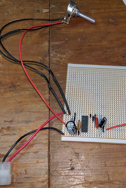
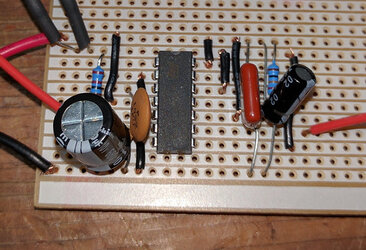
Here is my board layout (click for larger)
29403639391_05a4e6ab88.jpg

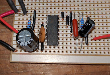
The red wire on the right is my PWM out. Because I ran out of space I soldered the diodes in-line with the wires to my pot, and covered them in heat shrink sleeving. Note the massive 680pf electrolytic capacitor instead of ceramic disc capacitors. As mentioned above, just in case this is the problem, I have ceramic ones on their way.

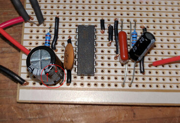
Here is more of a closeup:

29194866850_4eb7e4287f.jpg


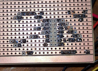
I have no pride in my soldering abilities. I don't have the steadiest of hands. This is the best I could do taking it nice and slow and spending several hours on it. It's not pretty, but I have checked for any bridging between strips, and I don't think there is any. Just as a precaution I hvae scratched the **** out of the insulating row between the strips to remove anything that might be bridging them, to no avail.

29194870320_8e1e1c1cf6.jpg

I'd appreciate any suggestions!
 
Last edited:
Well, this thread appears to be mostly dead, but I figured I'd post my follow-up anyway.

I finished my 556 based circuit but something is wrong.

I have double and triple verified that my connections match the diagram, and double, and triple checked for any shorts anywhere.

My behavior is that with the pot turned all the way counter-clockwise, the fan is at minimum speed. Turn the pot clockwise and nothing happens until the pot maxes out, at which point the fan suddenly switches to maximum speed. From this point if I turn the pot counter-clockwise again the fan stays at maximum speed all the way until I reach the minimum setting, at which point the fan switches to its minimum speed again.

I noticed that I didn't wind up with exactly the same components as the op. my 680pf - when I received my order - wound up not being a ceramic disc capacitor but rather was electrolytic, and thus polarized. I soldered it such that the negative pole was on the ground side, and figured it wouldn't make a difference, but maybe it does?

I have ordered another set of 680pf capacitors to check if this is the culprit.

Here is more of a closeup:

29194866850_4eb7e4287f.jpg

I'd appreciate any suggestions!

I have a feeling that 680pf cap you have is really a 680uf cap, post a pic of an unused cap showing the value of the cap.

edit: You do have the wrong cap (see pic below)

680uf.jpg
 
Last edited:
I have a feeling that 680pf cap you have is really a 680uf cap, post a pic of an unused cap showing the value of the cap.

edit: You do have the wrong cap (see pic below)

View attachment 183081


Holy ****, you are right, it is. I thought it was kind of odd it was so large, but I went with it.

The packaging they came in definitely says pF, but the writing on the side of the cap itself says uF.

I feel like I should have verified that. I work in quality and I know all abut incoming inspection, just didn't think to do it for my own home project!

Any chance the discharge from a capacitor literally a million times larger than intended might have done damage to the rest of my parts or the IC, or should I be OK to just remove the offending part and replacing it with the correct one?

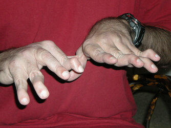
You think you have it bad :rofl: I soldered all the parts on that little board with these hands.

Double jointed? Nice.

Yeah, I just have ordinary hands, but they are on the large side making detail work difficult. Add to that that they shake while doing fine detail oriented work as well. Makes it difficult.

Strip boards are tiny enough for me, and just about the smallest I could possibly work on. Anything surface mount or professional PCB would be a pipe dream for me.
 
Last edited:
Double jointed? Nice.

No, not double jointed, it's Swan neck deformity as a result of Lupus. It's affected my tendons and ligaments in the bone joints in my hands, arms, shoulders, knees and feet.

As for that cap, it won't hurt anything having the wrong value in the circuit.
 
I use this zoom-stereo-boom-microscope, I find I can control my hands better when I can see that small :)

I tried using something like that a few years back when I - two weeks after launch - slipped with a screwdriver when taking the cooler off of a Radeon HD 7979 in order to try to custom mount an h80 cooler on it.

They had these stereoscopes in the labs at worn so I triwd using one to fix the traces I accidentally cut. I was never able to do it.
 
Got my 680 pF capacitors and replaced the incorrect one today. Everything works :)

At first I thought it didn't, because there is a noticible delay in the circuit when going from the minimum setting up to higher settings. Presumably this has to do with capacitors charging? The delay appears to be minimal when shifting between non-lowest settings though.

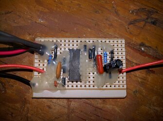
I have done a ****ty hotglue strain relief/conformal coat because I was concerned about things shifting and conductors touching. Once it dries and I cut my board down to size I will post my (very ugly, but functional) pictures.
 
So, the PWM controller is done, and works great.

It's butt ugly, but it works great.

Here it is, sealed up with some hot glue, just so nothing shifts around and causes a short:

28930893273_6eb6c70025_b.jpg

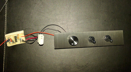
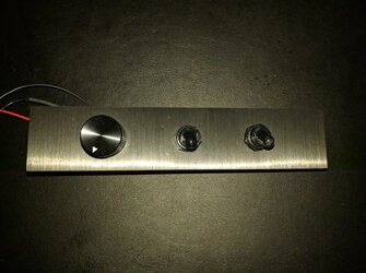
I ordered a 3 pack of extra drive bay covers from corsair so I could chop one up and install switches and the pot with a dial on it to control my fans.

29263885430_bb1872e9bf_b.jpg


Middle switch: Fans On/Off
Right Switch: Fans Manual control or auto control based on water temp (if middle switch is on)
Dial: Controls fan speed via PWM

29553832825_c5a752cffc_b.jpg


Turns out the front panel on Corsairs Obsidian series bay covers is textured sheet metal. It is glued somehow to the plastic part of the bay cover underneath. I pried the metal part off using a contractor knife. The goo from the glue was intense. Took lots of goo-off to clean both sides. Then I carefully drilled/dremeled holes to fit my two switches and my pot dial in the metal front, and went nuts with my dremel on the plastic to make everything fit in the back.

I was going to glue them back together again, but I think the screws that tighten the switches and pot to the panel do the job, so it's not needed.

The hole locations weren't exactly perfect. I measured them precisely, but kept slipping with the damned drill when I went to drill them. Should have used a punch to start the holes, but I couldn't find mine. I don't think I can tell that they are misaligned, but if it winds up bothering me, I have three more spare Corsair drive covers to re-do it on. :p

I wiped the damned thing down, but it appears to be statically charged, and clings to all the dist from my dremeling. Will have to do a more careful cleaning when I put it all together.
 
Back