• Welcome to Overclockers Forums! Join us to reply in threads, receive reduced ads, and to customize your site experience!

The Thing

Overclockers is supported by our readers. When you click a link to make a purchase, we may earn a commission. Learn More.
So I am fitting my board into my HAF932 and getting a feel of where I will need to add some holes... So far, I have the 6 lower screw mounts lined up with what already is in the case... trying to find a pen to mark a few upper holes for extra stability...

I am wondering too, for extra support, I have some "double side foam tape"... similar to the cushon tape that is on some select mounting bracket back plates for heatsinks... I want to use some of it on the bottom of the board. I am talking small peices. Should I be wary of where I stick it on the bottom? Or am I safe since it is not "conductive" and it will be small amounts in the void areas?
 
Double sided foam to support the board?

I wouldn't do that, but then I'm also not familiar with using double sided foam for heatsinks, either.

Take your time and drill out the holes and tap them to receive the offsets. On Tanker, I didn't put an offset under every hole on the mobo - a couple I skipped because the mobo backplate had no metal there (it was a cut out area). As long as you don't skip two mobo holes in a row, you should be fine.

Congrats! :D
 
Well not on the heat sinks, but the mounting plate on the bottom side of th mother board. I was only wondering since a lot of the holes sit over open space just next to the case plate that holds the motherboard... but I can still get about three drilled. I was just going to offset with thick foam cushion tape in the areas that I can't drill or fit an offset... Just added support. I will offset at the very top like the rest of y'all did as well... I'll post some annotated pics soon... But for now, bed time for this guy
 
I knew which side of the board you meant. I've not heard of using that material behind a mobo before though.

[Edit: Oddly, just saw a video with a dedicated water cooler unit, that used that 2 sided mounting tape.].

Far better to use the mounting tape, than to have the leads on the board's back side, contact the mobo plate and short out the mobo.

If you put a strip of electrical tape over the middle of the mounting tape, that would really cut down on the grip it had on the mobo (or just use smaller strips of the mounting tape).
 
Last edited:
Some of that double-sided mounting tape holds very, very firmly. I wouldn't use it. I wouldn't want to chance stressing the motherboard too much when you eventually need to remove it from the case.
 
So I am fitting my board into my HAF932 and getting a feel of where I will need to add some holes... So far, I have the 6 lower screw mounts lined up with what already is in the case... trying to find a pen to mark a few upper holes for extra stability.

This afternoon I'll start a thread and post pics of what I did to my HAF932 last weekend to supply mounting points for my Supermicro. I took good pics throughout the process. I'll say this. It is in there... SOLID! :D
 
This afternoon I'll start a thread and post pics of what I did to my HAF932 last weekend to supply mounting points for my Supermicro. I took good pics throughout the process. I'll say this. It is in there... SOLID! :D

Excellente! I will stick with the screw mounting only then... just wondered how secure (wobbly from occational movement) the board would be, so the tape came to mind for added stability...

I also am having a hard time finding the thread you replied to me on about the tap/die/punch thing... I was going to add those to my 1st post in the build log as I update with Build pics and even links to the tools for pricing. the the size/name/type will do... I can google the rest, and run by the Home Depot to buy. Should have done it earlier, but this build will take me a few days or more... 3 Kids and work leave about 30-60 min at night to play with my stuff! But that is NO complaint!!
 
I thought I might find you were done Steve:) My wife signed for my Mobo this morning... I asked her to turn on all lights, park her car out in the driveway and peek out the window. She drew the line when I suggested she put on her running sneaker's in case she had to sprint after him. :)

Gonna need an all nighter tonight to get it posted...stuck at work for now... :(
 
Excellente! I will stick with the screw mounting only then... just wondered how secure (wobbly from occational movement) the board would be, so the tape came to mind for added stability...

I used the included standoffs for all my mounts... the threading on those standoffs is 6-32. I literally spent $1.09 on my mod for some 6-32 nuts... more in a little while. Taking the afternoon off.

Don't rush it Dave... you've waited this long. Make sure you do it right! :)
 
you don't even need to tap threads if you don't wish to. You can simple drill holes and bolt the standoffs to the board with 6-32 nuts. That's what I've done with my SM board. I think this is what Harlam was alluding to.
 
Sweet! I will do that with the 6/32 nuts and my dremel for the holes...

PICS? yeah yeah yeah, I will bump the thread (look at first post for edit) with new pics! gotta take some... I will when I start the build process tonight or tomorrow.
 
Anyone got a link to a diagram that shows how to install the power/reset/status light cables to the mobo pins? i dont have the pin mount connector to put them on to plug into the mobo.. so I will be doing it "blind"
 
download the manual

If you can't find it, I'll email you mine. It's a different model, but the I/O pinout should be the same.
 
Steve get a bright light and a child with good eyes;) 
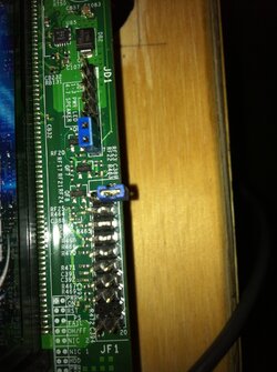
the schematic is on the board, and its a standard configuration. I'll see if I can take a Macro of it and label it for you. They intend for folks to just D/L it. http://www.supermicro.com/support/manuals/index.cfm

Right where I have the blue jumper is the Power. You can see the schematic next to the CPU2 memory modules. Honestly PWR on is probably the only one you'll need...maybe the reset.
 

Attachments

  • schemo.JPG
    schemo.JPG
    210.1 KB · Views: 168
Last edited:
AHHH I am an r-tard... but in my defense, it was dim in my room... and I will be 30 soon :p (not that old, but hey, I am just depressed that I will be outta my 20's!! LOL!)
 
No man, scratched my head for a good 10 min trying to find them. I thought it was the ones above that. Using a jumper on the Pwr led and speaker connectors got me no were ! :)

Also I only have 1 out of the 3, 8 Pin CPU plugs in. It's running fine. Leanardo is using 2.
 
AHHH I am an r-tard... but in my defense, it was dim in my room... and I will be 30 soon
Scratch that excuse, bud. I'm 50, and I had no problem! (ok, I did need to squint and use an LED headband)
Also I only have 1 out of the 3, 8 Pin CPU plugs in. It's running fine. Leanardo is using 2.
Nope, using all three EPS-12V connectors. But I assume only two are needed. You only have one 8-pin connected? And it's Folding....or not Folding yet?
 
Back