• Welcome to Overclockers Forums! Join us to reply in threads, receive reduced ads, and to customize your site experience!

Not-So-DIY Outside Corner Brackets

Overclockers is supported by our readers. When you click a link to make a purchase, we may earn a commission. Learn More.

Navig

Senior Case Master
Joined
Dec 7, 2003
Not so DIY outside corner brackets


Bracket5in.jpg


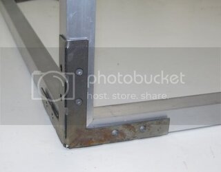
The goal of this project is to externally join a corner where 3 square tube frame elements meet.


This sub project is a close relative to my recently posted DIY Inside Corner Bracket.


http://www.overclockers.com/forums/showthread.php?t=699004


The history of this project goes back several years to my Exoframe Project.


http://www.overclockers.com/forums/showthread.php?t=597792


Specifically to this page of the build log:


http://www.overclockers.com/forums/showpost.php?p=5760709&postcount=8


While my DIY plastic brackets have worked great, they are a pain to build, and maybe not as strong as I like (glued joint).


So thanks to

Matt at Mione’s Solidworks for the CAD work

and

Erik at Norcal Laser for the cutting.
 
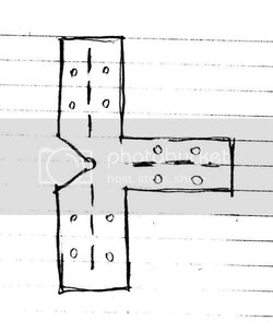
I started with just a drawing:


Prototype3.jpg


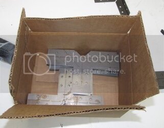
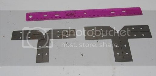
Mione’s Solidworks rendered it to CAD for me and Norcal Laser cut it from 18 gauge steel.


Boxofbrackets.jpg


Bracketscut.jpg


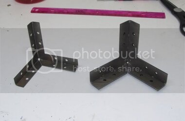
I’ve got 2 types of brackets--one based on ½” thick leaves, which when paired with ¾” square tube framing elements will leave a reveal--and one based on ¾” thick leaves for a full corner cover.


Also notice that there are thin slots cut out along the fold lines to guarantee accurate folds.


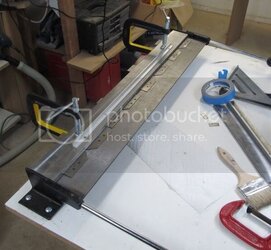
The next step was to bend these flat shapes into brackets. I’ve got a $40 bending brake from Harbor Freight Tools.


Bendingbrake2.jpg


Makes quick and accurate work of bending even multiple brackets at the same time.


2 folds on each bracket and they look pretty good:


Afterbends.jpg


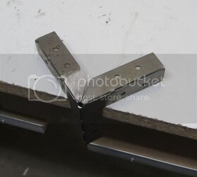
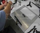
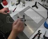
At this point they are actually pretty stable, but we are going to go ahead and solder the seam.


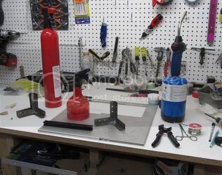
First of all, gather your tools:


Solderingtools.jpg


1) Something safe to solder on.
2) Safety tools: water spritzer, fire extinguisher, something to hold hot brackets with.
3) Soldering tools: flux and brush, propane plumber’s torch, silver solder.
4) Jig to hold the bracket.
 
Step #1
Prep


Preppingsurface.jpg


I prep both side by sanding and cleaning.


Step #2
Apply Flux


Fluxed.jpg


Be generous and apply in the distribution where you want your solder to go.
 
Step #3
Solder


Apply heat until the flux boils off, then melt the solder and it will flow over where the flux was, and down thru the seam.


One side:


th_MVI_5092.jpg

(Click for video)


And the other:


th_MVI_5091.jpg

(click for video)


Soldered:


Soldered.jpg


Step #4
Grind down the joint


I used a dremel with a sanding drum followed by a hand file.


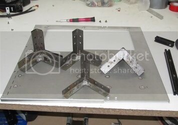
Brackets:


Bracketssoldered.jpg
 
How exactly do these brackets work?


First build your corner.

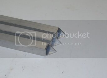
I like to use ¾” diameter square tube, with 1/16” thick walls (strong but light weight, good for computer builds).


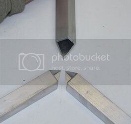
Double miter the ends:

Mitered2.jpg


You can square cut the ends, but using the double miter is 1) More stable 2) Does not require an end cap.


Double miter’d ends will meet like this:


Mitered1.jpg


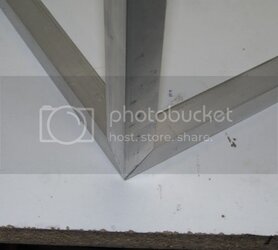
Giving a super pretty AND more structurally stable joint:


Mitered3.jpg


Add your screw holes:


Mitered4.jpg


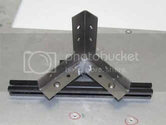
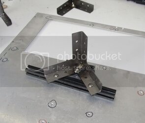
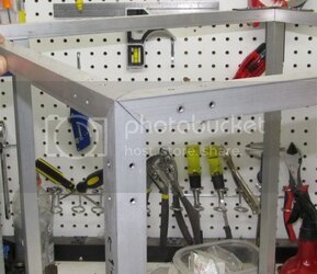
And there you have a 3 way bracket’d corner:


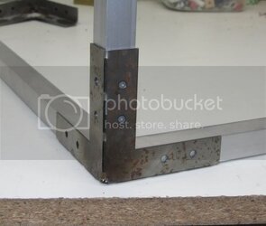
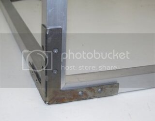
Bracket75in.jpg


or with reveal:


Bracket5in.jpg


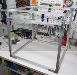
Throw some joints together and you have an Exoframe!


Exoframe2.jpg


Super light but super stable:


th_MVI_5112.jpg

(click for video)


And in case you were wondering, yes that is a new exoframe. It is being built on request for an ocforums member. And it will soon have its own thread.


.
 
Back