- Joined
- Dec 31, 2004
- Location
- Osan AB, South Korea
[EDIT 3: 10 Feb 2013]
When you put the TIM on the bare die, make sure you spread it out over the surface completely. Don't put a small dot on the center and hope the pressure of the IHS will spread it out: it won't! Here's what happens if you try to do that: http://www.overclockers.com/forums/showthread.php?t=726517
[/EDIT 3]
[EDIT 2]
A few people seem to be confused about what's going on here, so here's a quick primer:
CPU Die: This is the actual silicon (not silicone! silicone is used in breast implants, silicon is used in processors") ) that makes up the transistors of the CPU. That's the dark colored long rectangular thing on the PCB.
) that makes up the transistors of the CPU. That's the dark colored long rectangular thing on the PCB.
PCB: Printed Circuit Board. This is the green plastic base with all the little electrical traces on it.
IHS: Integrated Heat Spreader. This spreads out the heat created by the die onto a larger surface area. When you increase the surface area that the heatsink touches, you increase its efficiency (to a point). The IHS also protects the die from being crushed by today's massive air coolers!
TIM: Thermal Interface Material. This is a (usually liquid) material that enhances the interface between to thermally-connected surfaces. If you think about it, on a microscopic scale, there are tons of nooks and crannies and general irregularities on any surface. TIM fills in these gaps between the two surfaces.
De-Lidding: The act of removing the IHS.
The problem with Ivy Bridge is two-fold: first, Intel was using crappy TIM on the die-IHS interface. Second, the IHS was mounted too high on the PCB, and there was a significant gap between the die and the underside of the IHS (when you remove the IHS and all the TIM and glue, then place the IHS back on the die, you find that the bottom of the IHS doesn't contact the PCB, meaning Intel probably used WAY too much glue or TIM to attach the IHS). Both of these things contributed to an inability to tranfer heat out of the die and into the heatsink. By de-lidding, you can replace the TIM with higher-quality TIM, plus remove the gap and have the IHS directly contacting the die.
[/EDIT 2]
In case you're curious, I followed the directions here exactly. I used CoolLaboratory Liquid Ultra at both the die/IHS interface and the IHS/waterblock interface. Very cool stuff...the consistency is like liquid (hot) solder; it forms globs exactly the same way. Bit of a pain, but you can spread it out VERY thinly on the die and IHS.
Here are my initial results: I was previously running at 4.7GHz (47x100) at 1.412 vcore, fixed. I ran a few stress test programs before I de-lidded and recorded the instantaneous temperatures at the 2, 5, and 10 minute marks, as reported by CoreTemp (1.0 RC4) and Asus AI Suite (2.01). Then I did the same thing after de-lidding and compared the difference. I also have a water temperature sensor which is in my loop immediately after the CPU and GPU and before any rads, so it's in the "hottest part of the loop" (though such a thing doesn't really exist ). I visually recorded this at the same intervals as well, however, it turned out that the water temperature did not change significantly. Room temp was maintained between 74-75F (around 23.5C).
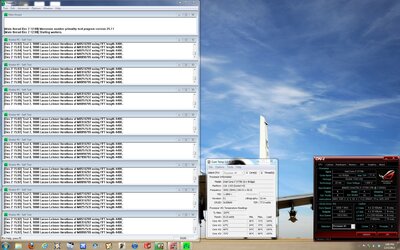
Prime95 was run on Blend, IBT was run at 1024MB.
The Average CoreTemp number is the average of the four core temperatures reported by CoreTemp at the time indicated. As you probably know, temperature measuring tools tend to show random jumps in temperature every now and then, and I don't really trust any of them. Still, you can clearly see a ~15-20C drop in temps across the board.
Also, I ran IBT just for fun for 100 iterations and my temps in CoreTemp never went above 67C. Amazing. I was hitting 90C before de-lidding.
I should also mention my cooling setup, which is in my sig, but may change in the future: EK Supremacy on the CPU, EK full-coverage acetal block on the GTX 680, MCP35X, 1x120mm rad with a Delta fan, and 1x180mm rad with a Silverstone fan.

Next up, I'm going to up the voltage and try for 5.0GHz!
When you put the TIM on the bare die, make sure you spread it out over the surface completely. Don't put a small dot on the center and hope the pressure of the IHS will spread it out: it won't! Here's what happens if you try to do that: http://www.overclockers.com/forums/showthread.php?t=726517
[/EDIT 3]
[EDIT 2]
A few people seem to be confused about what's going on here, so here's a quick primer:
CPU Die: This is the actual silicon (not silicone! silicone is used in breast implants, silicon is used in processors
) that makes up the transistors of the CPU. That's the dark colored long rectangular thing on the PCB.PCB: Printed Circuit Board. This is the green plastic base with all the little electrical traces on it.
IHS: Integrated Heat Spreader. This spreads out the heat created by the die onto a larger surface area. When you increase the surface area that the heatsink touches, you increase its efficiency (to a point). The IHS also protects the die from being crushed by today's massive air coolers!
TIM: Thermal Interface Material. This is a (usually liquid) material that enhances the interface between to thermally-connected surfaces. If you think about it, on a microscopic scale, there are tons of nooks and crannies and general irregularities on any surface. TIM fills in these gaps between the two surfaces.
De-Lidding: The act of removing the IHS.
The problem with Ivy Bridge is two-fold: first, Intel was using crappy TIM on the die-IHS interface. Second, the IHS was mounted too high on the PCB, and there was a significant gap between the die and the underside of the IHS (when you remove the IHS and all the TIM and glue, then place the IHS back on the die, you find that the bottom of the IHS doesn't contact the PCB, meaning Intel probably used WAY too much glue or TIM to attach the IHS). Both of these things contributed to an inability to tranfer heat out of the die and into the heatsink. By de-lidding, you can replace the TIM with higher-quality TIM, plus remove the gap and have the IHS directly contacting the die.
[/EDIT 2]
In case you're curious, I followed the directions here exactly. I used CoolLaboratory Liquid Ultra at both the die/IHS interface and the IHS/waterblock interface. Very cool stuff...the consistency is like liquid (hot) solder; it forms globs exactly the same way. Bit of a pain, but you can spread it out VERY thinly on the die and IHS.
Here are my initial results: I was previously running at 4.7GHz (47x100) at 1.412 vcore, fixed. I ran a few stress test programs before I de-lidded and recorded the instantaneous temperatures at the 2, 5, and 10 minute marks, as reported by CoreTemp (1.0 RC4) and Asus AI Suite (2.01). Then I did the same thing after de-lidding and compared the difference. I also have a water temperature sensor which is in my loop immediately after the CPU and GPU and before any rads, so it's in the "hottest part of the loop" (though such a thing doesn't really exist
). I visually recorded this at the same intervals as well, however, it turned out that the water temperature did not change significantly. Room temp was maintained between 74-75F (around 23.5C).Prime95 was run on Blend, IBT was run at 1024MB.
The Average CoreTemp number is the average of the four core temperatures reported by CoreTemp at the time indicated. As you probably know, temperature measuring tools tend to show random jumps in temperature every now and then, and I don't really trust any of them. Still, you can clearly see a ~15-20C drop in temps across the board.
Also, I ran IBT just for fun for 100 iterations and my temps in CoreTemp never went above 67C. Amazing. I was hitting 90C before de-lidding.
I should also mention my cooling setup, which is in my sig, but may change in the future: EK Supremacy on the CPU, EK full-coverage acetal block on the GTX 680, MCP35X, 1x120mm rad with a Delta fan, and 1x180mm rad with a Silverstone fan.

Next up, I'm going to up the voltage and try for 5.0GHz!
Last edited: