• Welcome to Overclockers Forums! Join us to reply in threads, receive reduced ads, and to customize your site experience!

Non-Ref 9800GTX+ Vmod

Overclockers is supported by our readers. When you click a link to make a purchase, we may earn a commission. Learn More.
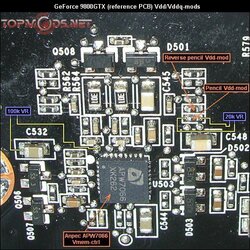
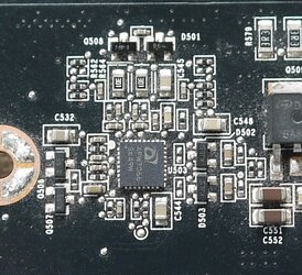
Mem is almost certainly the square job along the top just to the right of the input power connections.
That RTsomethingOrOther middle lower pin is most likely FB, but it'll be some other voltage rather than vcore or vmem.
PLL or something maybe.

I could be wrong of course.
 
Last edited:
I'm just this guy, you know?


On ALL* voltmods, measure across the vsense-to-GND resistor first, you want your VR to be 10x-15x the measured value across that resistor. Less than 10x and you have a big voltage bump even set as high resistance (lowest additional voltage) as it'll go. More than 15x-20x you have very little bump until the end of the VR travel when a tiny change makes a big voltage change.

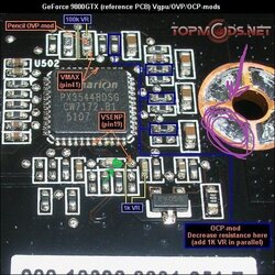
For vcore the 1k VR is mod is the place to start.

For memory the 20k VR is the place to start.

Go for basic vcore and vmem mods first, then if you run into OVP/OCP issues you can start diving into the additional mods.


Lastly, make absolutely positively 100% sure the VR pins you use are set to the highest possible resistance when you turn the card on.
To check, measure between the unused VR pin and the middle VR pin, you would little to no resistance. That means the other end VR pin to middle pin is maximum resistance.
Failure to do this can result in booting at way higher than survivable voltages and letting the magic smoke out.


* There's always that one (1) that you have to do things differently, but if you're not modding bizarre top end stuff, don't worry about that one.
 
sorry shawn wife off this weekend getting online is kind of hard- WOW nice to see you still around Ed

Looks like you going to have to test to see which controller is for the memory I trust the pic's you found but I also see the rt9259 is use for memory on the 9800 gtx+ to

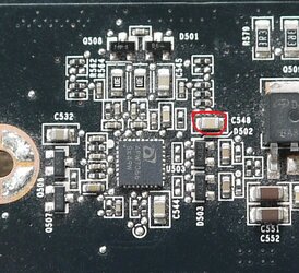
there should be 2volts going to the memory test what I circled in red(wish i could see the traces in the pic's) and then you could test pin four on the rt9259 if not to small :) bad card to learn on

As for OCP might be able to solder to the cap's instead of the resistors circled in blue to make it easier just need to take ohm reading to make sure they are the same

OVP looks straight forward

P1360690.JPG
 
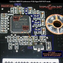
Thanks Bob, I'll pick away at this through the week and see where I get to. I think I have some pots upstaits in a box that I got from BMWBaxter when I bought out his cold equiptment. So I should be good. Have to find some tiny wires though. To get this straight in the Vgpu pic 1K resistor and can I just use the closest pad to the primarion chip and run the other to ground? Same for the 20K on the mem. The less I have to solder around those pads is likely the better. I also have a couple of dead mobos here I'm going to practice on before I try the real deal.

Thanks Q_F, I think Ed is likely on the right track, that 7066 chip is a mem controller as well according to info I dug up and the RT9 is at the other end of the card maybe for PLL like Ed said , I haven't a clue but that 7066 is directly below the mem power circuits on the top of the board. I have time off this coming week. Tomorrow is another "family" day so no go on the fun stuff. Maybe Tuesday. I also want to set up a LN2 session for later in the week so have to put some time aside for that. I'd like to get this done beofre the end of the TC to get a better score for the netburst sub.
In that pic you're saying check that resistor to ground for 2v?
Also could one of you guys maybe point out some good read points to solder a molex to. I've seen that in a lot of mods and looks like the easiest way to keep an eye on your voltage
 
Last edited:
Yeah saw the site you got these pic's form looks good -I was trying to kill two birds with one stone if the cap was reading 2 volts then most likely that was for memory and you would have a read point for vmem but I see the site has a pic of the volts read points already

:) and I just realized this is the same mods I just did on my 8800gtx don't know I didn't see that last night the 8800gtx has px3540(same pin out)- OCP looks to be wrong
 
That resistor you circled only gave ~.4v but the ones they suggested on that page gave me the 2.0v.
I found my pots and have what I need to do this. Got my fingers crossed and hopefully it works.

And if I understand Ed correctly when I power up after mod make sure both VR are at their highest reading? So 20K and 1K respectively? Does it matter which pins on the VR you use?
 
Yes 20k and 1k- would like to see you take your own Ohms readings most people would go 20x on the Ohms reading I like 15x on the Ohm reading I get- on the VR yes the middle pin allways- then one for the outer pins which pin you choose will determine if you turn clockwise or counterclockwise to increase the voltage
 
Last edited:
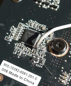
Well going to ground on the Vgpu didn't work, I'll have to try soldering to the other point tomorrow. Man that was a b**ch getting it to stick to that little pad.
 
First melt some solder on the tip of the iron then try to get to take where I circled in purple(you can solder to any ground on the card)then get some more solder on the tip of the iron then run it across the wire into you get some solder on the wire then bring the wire to where i pointed out in purple and take solder iron and melt the solder together

I can't solder for nothing but that's what works best for me you might want to use a ground where the power plugs in- I find the closest ground to where I am going to mount the VR

You'll get it just stick with it

18_9800gtx_vgpu_ovp_ocp-mods (1).jpg

edit: and another reason to take ohm reading before you solder anything so you can retest the readings after you solder the wire on (at the end of the wire) to make sure everything is still good
 
Last edited:
Yeah that was my bad. I just assumed it was the same. I was having trouble with that tiny little pad. I had the wire soaked with solder but getting it and that little pad hot enough to stick together at the same time was a real challenge. I'll have to take another look at it today if I can. According to that pic they went from the pad to the end of that resistor. I'm thinking maybe that's what I need to do

EDIT: I have tried to day to get a readin across pin 19 and that pad and it's almost always 0. Sometimes it'll come up .001 or .002. I don't know if it's me or what but that doesn't seem right.
 
Last edited:
That's not what I did. I checked betweem then. I figure my last attempt didn't work cause my solder broke. I had it glued but I still wiggled it too much I guess.
 
you can test the cap right next to that pad to the left that I mark in green (capacitors are brown and resistors are black)if it reads the same than test for conductivity between pin 19 and where I marked green if you got conductivity you can try that point to solder the wire to if think it might be easier

18_9800gtx_vgpu_ovp_ocp-mods (1).jpg
 
I'm going to try again today but the reading on that pad is only 12.8 Ω. So that would make a 1K vr too big correct. I would want something @ 128 Ω correct. I have 100 and 200 Ω VRs here so would 200 be the better choice?

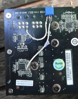
I successfully soldered a 200Ω VR in the circuit. Now the card powers up but I can't seem to get a volt reading at all and in windows GPUz reads 0s for core and mem speeds. I cranked the resistor down and had a funky screen crash and then no video. Seems it messed i=up the board bios did a clr cmos and it still works but not sure if I'm getting what I want here.
 
Last edited:
I would remove the ground from the VR then boot up the board and see if you can get a volt reading when voltage reads 0 volts most likely OVP kick in if you do get a 1.3 volt reading (think that is the stock reading) use the 1k VR and see what happens-Good thing for OVP and OCP :)
 
Before I modded on the high side of those caps it was 1.8v on the low (read point) was 1.155v stock for the card. After mod neith side reads any voltage. The original reading on the pad to ground was only 12.8 Ω. That's why I went with the 200Ω VR. I think the voltage did come to life at some point, that's why it crashed but... Now correct me if I'm wrong. I would have to get below the original read of 12.8Ω before the voltage would go up right. So that leaves me very little room to adjust wouldn't it?
 
yes- I am asking you to remove the ground for the VR to see if you shorted anything out if you get the same reading or should I say lack of then you will know-you could take a pic of that pad with your phone then you can zoom in to make sure the cap next to it didn't get shorted and lowered the Ohms to that pad
 
Ha way ahead of you Mike. Took one already today. Itlooks very clean to me.

solder.JPG vr.JPG


Jusr reread what you wrote up there. That reading was after running this yesterday so I know the card works with that 12.8 ohm reading. Wanted to run something before I go and break it. So I don't think there was a short. I also measured the wire after I soldered it and it was where it should have been

image_id_1676613.jpeg
 
Looks clean but as long your able to zoom in on your phone to see a clearer pic -but its easy to remove the ground wire from the VR to make sure it boots as it should if it don't, the ground wire could need to be solder to the other pin on the VR .I alway bend the pin over that I am not using so I don't get confused

And plenty of room to adjust if it does call for a 200 ohm VR
 
Back