• Welcome to Overclockers Forums! Join us to reply in threads, receive reduced ads, and to customize your site experience!

ripped off smd cap off my p4c800

Overclockers is supported by our readers. When you click a link to make a purchase, we may earn a commission. Learn More.

QuickFast

Member
Joined
Dec 21, 2011
Location
Nerwport,NC
I think it was a capacitor no markings and lite brown my question is can i replace it with a regular capacitor between the two red marks in pic and if i can how would i know what size capacitor
 

Attachments

  • 20130427_200801-1.jpg
    20130427_200801-1.jpg
    307.6 KB · Views: 134
What color was it? What're the markings on the IC it's right next to?
 
Looks like it might have torn the trace out with it, hard to say. The datasheet thoughtfully gives some numbers for capacitance so that's easy enough. If the trace got torn you'll need to fix that, but some fine wire should do the trick.
 
Can you post a couple pictures? First the chip with the passive components around it, Second, the original picture, without the marks.
 
Got the board up and running again couldn't find a capacitor to solder on so i just soldered a piece of wire from point A to point B the funny thing is the Vdroop seems to be gone and it now over voltting the cpu by .016 volts but the real test will be when i take the board over 1.7 volts hope the board last through one more nite of benching in till i can find a new capacitor
 
That was a filtering cap. You should actually put one back on there. It is most likely a 0.1uf or 1uf; most likely the latter.

I could identify what it is, if you give me those SS.
 
Hey Dolk thanks for looking out hope these pic will do the rest of the board is covered in plastic dip if you need more pic i could peel the plastic coating off.Would i be able to solder a cap in line with the wire i have all ready solder to the board because soldering skills sucks and i'am blind as a bat it took me forever to get the wire solder right
 

Attachments

  • 20130427_200801-1.jpg
    20130427_200801-1.jpg
    263.8 KB · Views: 123
  • 20130429_000753.jpg
    20130429_000753.jpg
    957.9 KB · Views: 128
  • 045f5c44_vbattach14448.jpeg
    045f5c44_vbattach14448.jpeg
    78.3 KB · Views: 120
It looks like it is a 1.5 or 3nF cap that sits between pin 18 and 17. This plays heavily in the assumption of the current sense loop. It would be best to replace the cap.

I do not have a good eye for size, either Bob will have to say what it is, or you can give me the length of the smd.
 
0603 it looks like.
I'd put the cap back too, without a scope its hard to say how needed it is.
 
thanks guys but right now curiosity got the best of me, want to see if Vdroop is gone with out that cap if Vdroop starts back up at 1.7-1.8 volts i'll solder a .001uF(the closest i got right now)and 27k resistor for Vdroop hope curiosity don't bite me in the ***
 
Just as long as you do not short you should be fine. There must always be a reference between the two lines.
 
She still lives after 4 hours of benching had no Vdroop that's because of the over volting that was happening for example 1.6 volts = 1.616\1.7 volts = 1.744\1.750 volts =1.808 i was hoping the Vdroop that was happening before i ripped that cap off was holding me back but looks i might just need LN2 to push these Northwoods further
 
Science Time:

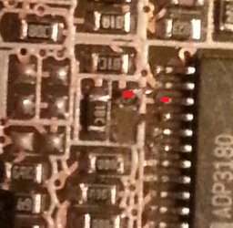
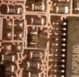
If the pins in question are in fact the CSSUM and CSCOMP, which are the current sampling coupled pins than we can assume the rest: When this cap is removed it will create more noise for the CSCOMP line. This will skew the result for CSSUM, most likely adding more to the result. This will cause the Vdroop to be corrected in the case of Overclocking, it will be able to provide the extra current and voltage needed. In normal cases, it may be dangerous to keep the cap removed, since the correction will be so accurate, higher currents and voltages may pass. This could damage something.
 
Back