- Joined
- Feb 18, 2007
So a couple years back I was picking up bulk lots of electronics in exchange for removing them... sometimes paying a small amount. Kept me very entertained, and between the PC trade and selling stuff on ebay, was worth while.
One lot was of old dental equipment... All kinds of neat stuff there! Even a dell XPS with a Core 2 Duo in it! But a couple inter-oral camera units were in the mix.
All this stuff was pretty darn old, but I took one of the best looking units, tested it, and sure enough it worked great... took a picture of it displaying on a TV and bang, $200 on ebay!!
Just last week I stumbled upon a unit I didn't sell, or otherwise part with, cause the case was cool! That thick, sturdy construction that any modder can appreciate. So below is the progress from yesterday morning going into last night. Wish I had more pictures, and please forgive the 1st image is not mine, but show's the exact same model the way it looked before I started.
First up... Parts list...
AcuCam Unit - Gutted
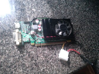
GeForce GT 430 - Got this with a board & cpu from Miahalen
Hipro PSU - From an old HP mid tower, 14A on the 12V line, outta be fine
The motherboard, cpu, and RAM I got off ebay, the seller accepted my offer and all in all it was < $60 shipped
Materials include...
Angle grinder cut off wheel
Grinding wheel
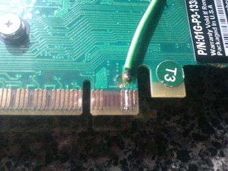
Rosin core solder
Bondo for the front bezel
Rustoleum primer, flat black, and blue
Some small screws & nuts (couple bucks at the hardware store, just eyeballed size)
Nylon washers / spacers for the PSU and MB spacing
Orange plastic spacers from an erector set
Tools...
Grinder
Plyers, for wiggling / ripping out old spot welded chassis dividers
Soldering iron
Sand paper
Drywall sanding block
Drill
Anyway... onto the build!
Our stock unit, not my image but it's the same model
Wish I had a pic of the origional inside layout. There was a mount for a transformer on one side, a tray in the middel, and the rear fan seen later, with the thumb screws; well that puppy slid out on a sled, with a high power light bulb that shined through the camera cable. I started out by cutting these mounts in half, and gave them some serious wiggling. After the welds broke, I was left with this pile:
And a clean slate!
On mini itx mods, small is key, so a fit like this is very rewarding to see
Mounting up the board was a no-brainer. There's only four holes and one expansion slot... not to mention it has great onboard IO. Bolts /w nuts & spacers will do just fine. Mark with a pencil, start a small pilot hole, remove the board, & repeat... Just bolt it down as you go! otherwise, it might not line up in the end. A disclaimer also, don't cut, drill, or anything like that, while components are installed or near by. I don't heed this advice, but I make sure to thoroughly blow everything off before powering it up.
So, I wanted to give this box a little more functionality. Let's face it, for just a board & PSU, no expansion, a smaller case could have been used. I like to get the most potential out of mods, so I found a video card that would fit in there... just barely... Or so I thought. Oh well, not gonna let that get in the way!
This seems a little... "hack", in the bad way but, it actually ends up working out great for my needs, and looks pretty bad ***.
The spacers I used for the MB mounting were the perfect size to go along with the case feet. This meant I could use just three screws, and still have the 4th corner safely off the chassis floor. I chose to put two bolts on the back side, to provide support for the IO jacks.
And I used similar spacers for the PSU... two bolts, opposite corners were used. Then in the remaining two holes, less spacing, but a bolt head also comes into play, to keep the PSU board corners from contacting the chassis.
As you can see here, I had to chop the top fin off the power supply's heat spreader in order to have the lid clear it. I don't think it'll effect it's cooling performance to a noticeable degree, since the system it's powering is low draw.
A little primer & paint to cover up the cuts... and another test fit. Cozy, but that's exactly what I was going for.
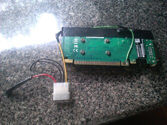
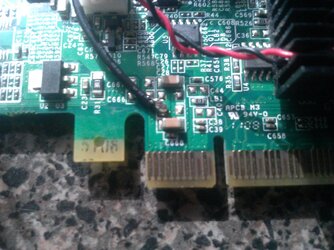
And, a little wiring to be done. The modern SATA connection added! lol
And the 4 pin CPU power removed!
I'd also removed the 2nd HDD / drive connection line.
This thing though... I like the way this switch looks, but I don't want the possibility of someone cutting the AC power to this thing, so I probably won't use it for that. I think, since it's an HTPC, I'll make that a "safety" for the power button, and also have it turn off the power LED. I don't know about you guys, but I'm not a fan of seeing LEDs all around my TV at night...
Anyway, lookin good!
And some finished / 99% shots...
Still would like to add some front USBs... we'll see. Right now I'm happy with the clean looks & the hot rod appearance of that GPU sticking out. The heatsink fins actually grab the case edge perfectly. It can't pull out, or move too much. Should have better cooling too!
One lot was of old dental equipment... All kinds of neat stuff there! Even a dell XPS with a Core 2 Duo in it! But a couple inter-oral camera units were in the mix.
All this stuff was pretty darn old, but I took one of the best looking units, tested it, and sure enough it worked great... took a picture of it displaying on a TV and bang, $200 on ebay!!
Just last week I stumbled upon a unit I didn't sell, or otherwise part with, cause the case was cool! That thick, sturdy construction that any modder can appreciate. So below is the progress from yesterday morning going into last night. Wish I had more pictures, and please forgive the 1st image is not mine, but show's the exact same model the way it looked before I started.
First up... Parts list...
AcuCam Unit - Gutted
GeForce GT 430 - Got this with a board & cpu from Miahalen
Hipro PSU - From an old HP mid tower, 14A on the 12V line, outta be fine
The motherboard, cpu, and RAM I got off ebay, the seller accepted my offer and all in all it was < $60 shipped
Materials include...
Angle grinder cut off wheel
Grinding wheel
Rosin core solder
Bondo for the front bezel
Rustoleum primer, flat black, and blue
Some small screws & nuts (couple bucks at the hardware store, just eyeballed size)
Nylon washers / spacers for the PSU and MB spacing
Orange plastic spacers from an erector set
Tools...
Grinder
Plyers, for wiggling / ripping out old spot welded chassis dividers
Soldering iron
Sand paper
Drywall sanding block
Drill
Anyway... onto the build!
Our stock unit, not my image but it's the same model

Wish I had a pic of the origional inside layout. There was a mount for a transformer on one side, a tray in the middel, and the rear fan seen later, with the thumb screws; well that puppy slid out on a sled, with a high power light bulb that shined through the camera cable. I started out by cutting these mounts in half, and gave them some serious wiggling. After the welds broke, I was left with this pile:

And a clean slate!

On mini itx mods, small is key, so a fit like this is very rewarding to see

Mounting up the board was a no-brainer. There's only four holes and one expansion slot... not to mention it has great onboard IO. Bolts /w nuts & spacers will do just fine. Mark with a pencil, start a small pilot hole, remove the board, & repeat... Just bolt it down as you go! otherwise, it might not line up in the end. A disclaimer also, don't cut, drill, or anything like that, while components are installed or near by. I don't heed this advice, but I make sure to thoroughly blow everything off before powering it up.
So, I wanted to give this box a little more functionality. Let's face it, for just a board & PSU, no expansion, a smaller case could have been used. I like to get the most potential out of mods, so I found a video card that would fit in there... just barely... Or so I thought. Oh well, not gonna let that get in the way!

This seems a little... "hack", in the bad way
but, it actually ends up working out great for my needs, and looks pretty bad ***.The spacers I used for the MB mounting were the perfect size to go along with the case feet. This meant I could use just three screws, and still have the 4th corner safely off the chassis floor. I chose to put two bolts on the back side, to provide support for the IO jacks.


And I used similar spacers for the PSU... two bolts, opposite corners were used. Then in the remaining two holes, less spacing, but a bolt head also comes into play, to keep the PSU board corners from contacting the chassis.


As you can see here, I had to chop the top fin off the power supply's heat spreader in order to have the lid clear it. I don't think it'll effect it's cooling performance to a noticeable degree, since the system it's powering is low draw.
A little primer & paint to cover up the cuts... and another test fit. Cozy, but that's exactly what I was going for.


And, a little wiring to be done. The modern SATA connection added! lol

And the 4 pin CPU power removed!

I'd also removed the 2nd HDD / drive connection line.
This thing though... I like the way this switch looks, but I don't want the possibility of someone cutting the AC power to this thing, so I probably won't use it for that. I think, since it's an HTPC, I'll make that a "safety" for the power button, and also have it turn off the power LED. I don't know about you guys, but I'm not a fan of seeing LEDs all around my TV at night...
Anyway, lookin good!


And some finished / 99% shots...


Still would like to add some front USBs... we'll see. Right now I'm happy with the clean looks & the hot rod appearance of that GPU sticking out. The heatsink fins actually grab the case edge perfectly. It can't pull out, or move too much. Should have better cooling too!
 )
)


 Will report back after tying a better supply.