-
Welcome to Overclockers Forums! Join us to reply in threads, receive reduced ads, and to customize your site experience!
You are using an out of date browser. It may not display this or other websites correctly.
You should upgrade or use an alternative browser.
You should upgrade or use an alternative browser.
Codename XmasList project
- Thread starter SwartHack
- Start date
- Joined
- Apr 3, 2015
- Location
- Planet Earth
- Thread Starter
- #82
Silver_Pharaoh said:Seems complex swart, but probably not once you get used to it eh?
really, if you understand the difference between raster and vector, its just learning a new UI...
Frankly, and typical of this type of software, I barley scratched the surface of functionality to do this.
And, actually I left out one important step. Corel Draw may be vector, but uses raster fills by default. (Yeah, what gives)
I have a black vector fill I used for the front panel, but had to find one on Corel shared library. Couldn't figure out how to make one.
I will need to go back through replacing the default raster fills with vector grayscale fills...
Yeah lame, but...
Supposedly the whole CAM/CNC industry is going to go raster?!? says the guy who did the front panel for me...
I am sure the price will compare nicely?Lochekey said:...will be interesting to see how it compares.
Buenas
- Joined
- Apr 3, 2015
- Location
- Planet Earth
- Thread Starter
- #83
OK SP, I hope you cranked the handle on your inter-web-a-thingy before you read this post!!
This post is also dedicated to Silver_Pharaoh, eh. Actually how bout include the entire Great White North, eh!?
To lay out the knob process to all youz hosers, eh..., ready to get cattywampus'd
So grab your two four eh, take a toque, and take off

(I've been thinking, I should start dedicating all my posts to someone or something, hmmm...)
I am going to give a quick Corel tutorial here, going through in more detail the pre-processing tasks.
I'm not going to show every mouse-click and sub-menu/etc. If you have used Paint before you are previously certified for this tutorial.
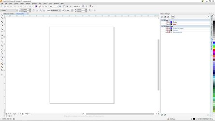
Starting from the very beginning, because its an important step, in that you get your dimensions/units set here.The is done in Corel Draw.

And you get this as an empty document.

So we go and File/import our jpeg, and as before we don't want to resize it here, just click enter to center...

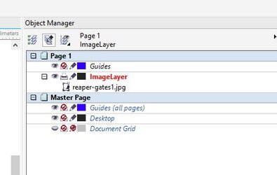
We get a new layer with a bitmap object, I renamed to ImageLater. (Note the eyeball for layer visibility)

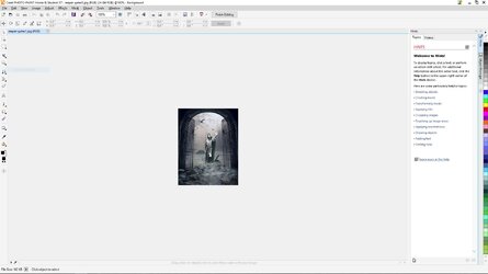
Now we are ready to edit: (this will shell you out to Corel Photo/Paint, which has a very similar UI)


So we are going to re-sample, just a fancy word for re-size, like in paint.
There are many other ways to achieve a re-sized image, but this is the most straightforward and seems to classify/group well.

It comes in default units of the Photo/Paint UI,

just change to match your original doc setup and go with default 300dpi. And we get this.
Note the huge size of the resized image. Do not worry about this....

Cause you hit the "Finish Button"...

And we are back in Draw with a sweet looking image to trace!!!

Select the bitmap in the Object Manager, and: (Selecting "High Quality Image")

And you get this!

Hell Ya, I want you to do that for me!
The "Power Trace" Tool opens

It is hard to tell, but it has already performed a preliminary traced with default setting.
Notice the "Trace result details", 1986 objets and 249 colors.
So lets start some processing. Anytime you mess something else you can revert to previous.It will autoupdate everytime you make a change.
For High Detail don't mess with the Trace Controls: detail and smoothing.You do want to set the options as show.

Then click over to the Colors tab.

This is were we will do the work! I figured out a better approach to grouping/merging shades during the pre-processing.
So by default as the original image was RGB, we get 249 unique RGB values.This is great if we were working in color output, but we are not.
"Color Mode" offers many options, one of which is gray scale(255 unique values)
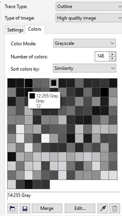
We switch and get 148 unique gray scale values. Which is WAAAYYY to many for this application.

You can use the color palette hover to identify values. Here I am comparing two of the darkest colors too determine lowest value.

I then switch the number of colors to 40. Why? Well I went through a number of choices.

Remember, it updates with every choice. Pay attention to the growing differences between original and preview.
Also I want to have about 10 shades, so figure about 5 times that many to a get good range, you'll see...

So now we want to start grouping/merging colors. I start with the darkest, because it will eventually be the background.
(Approach on grouping will be determined by nature of original image. In this case I have a lot of darks we need to merge, but we also need to conserve the lighter colors which will provide the detail)
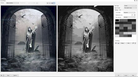
So here I pick all values under 30. The resulting color is some average, in this case I got 17.
The stripes show the area/extent of this shade.

So we continue grouping. As you do you really see the effect coming through that will define the etching layers.
I kinda loose the tree background detail, but I was expecting that.
I get down to 13 colors and am estatic, as it still looks great with significant detail...

We have 13 grouped objects with a total of 1085 curve objects. That's waayyy too many.

So we OK, the PowerTrace, and SHAZZAAAMMM.

In the end it should be one curve object/path per layer per shade. Otherwise the laser/software can't cope.
What we do now is create empty layers with the name of the shade, and copy the appropriate group to the layer and ungroup.
You can check the groups gray scale value in object properties.

So each layer should end up with the contents of the original group and look like this...

Now in a perfect world, we would select all the curves from each layer and "combine", but we cant do that yet...
We need to go through and simplify/merge more colors. This is where the busy work comes in, but is waaay easier now that we used the preprocessing merge technique...

Also we are going to eventually delete the 17 layer as it is the darkest, and will be the areas that don't get etched.
But we need to start by changing 17's, we don't want to be deleted, to 33's and copied to that layer.
We use the color eyedropper tool to identify the color we want to merge to, and then click all the object we want that color, then use "Move to layer.." tool.
I am not going to get into the total specific of what/why you merge or not. The biggest goal being maintaining detail, while simplifying
Here is an example of what we look at up closer

I can't just delete it. As then it becomes a hole and black anyway


So we user the dropper/fill tool

And now they match! Those two objects will merge when we run a "combine" on the layer.
For now we just leave it and it provides a edit crumb trail for us.

Ok, that's it up to here. I have some edit time to go through the entire image.
In part 3 we'll go through what I learned and review the final product.
Tots Zien
EDIT:
So I spent a few this morning working on an area:
You can see all the edit crumbs, being the circle areas that are the same shade as their containing object.
These are the edits I have made so far. Going through this section took about 15 minutes...

This post is also dedicated to Silver_Pharaoh, eh. Actually how bout include the entire Great White North, eh!?
To lay out the knob process to all youz hosers, eh..., ready to get cattywampus'd
So grab your two four eh, take a toque, and take off

(I've been thinking, I should start dedicating all my posts to someone or something, hmmm...)
I am going to give a quick Corel tutorial here, going through in more detail the pre-processing tasks.
I'm not going to show every mouse-click and sub-menu/etc. If you have used Paint before you are previously certified for this tutorial.
Starting from the very beginning, because its an important step, in that you get your dimensions/units set here.The is done in Corel Draw.
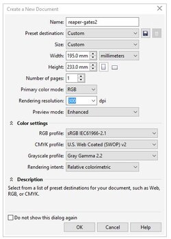
And you get this as an empty document.
So we go and File/import our jpeg, and as before we don't want to resize it here, just click enter to center...
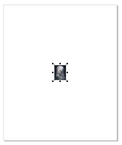
We get a new layer with a bitmap object, I renamed to ImageLater. (Note the eyeball for layer visibility)
Now we are ready to edit: (this will shell you out to Corel Photo/Paint, which has a very similar UI)

So we are going to re-sample, just a fancy word for re-size, like in paint.
There are many other ways to achieve a re-sized image, but this is the most straightforward and seems to classify/group well.
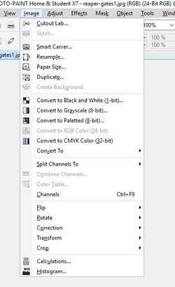
It comes in default units of the Photo/Paint UI,
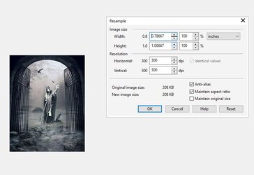
just change to match your original doc setup and go with default 300dpi. And we get this.
Note the huge size of the resized image. Do not worry about this....
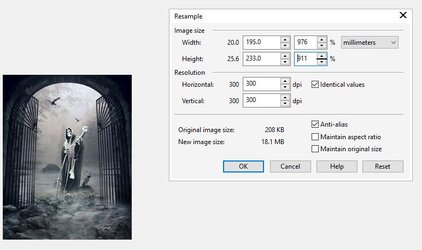
Cause you hit the "Finish Button"...

And we are back in Draw with a sweet looking image to trace!!!

Select the bitmap in the Object Manager, and: (Selecting "High Quality Image")
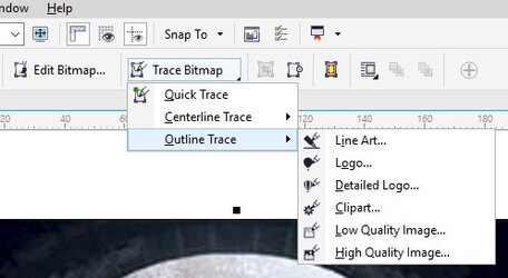
And you get this!

Hell Ya, I want you to do that for me!
The "Power Trace" Tool opens
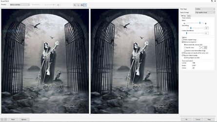
It is hard to tell, but it has already performed a preliminary traced with default setting.
Notice the "Trace result details", 1986 objets and 249 colors.
So lets start some processing. Anytime you mess something else you can revert to previous.It will autoupdate everytime you make a change.
For High Detail don't mess with the Trace Controls: detail and smoothing.You do want to set the options as show.
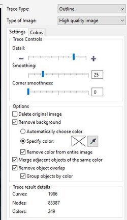
Then click over to the Colors tab.
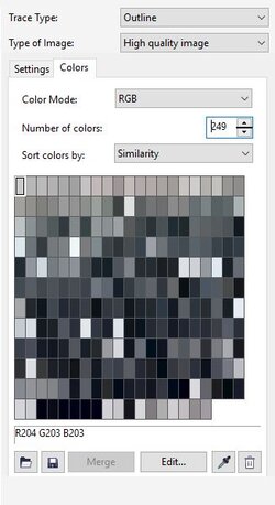
This is were we will do the work! I figured out a better approach to grouping/merging shades during the pre-processing.
So by default as the original image was RGB, we get 249 unique RGB values.This is great if we were working in color output, but we are not.
"Color Mode" offers many options, one of which is gray scale(255 unique values)
We switch and get 148 unique gray scale values. Which is WAAAYYY to many for this application.
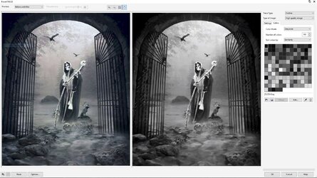
You can use the color palette hover to identify values. Here I am comparing two of the darkest colors too determine lowest value.
I then switch the number of colors to 40. Why? Well I went through a number of choices.
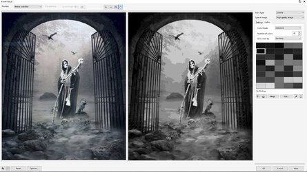
Remember, it updates with every choice. Pay attention to the growing differences between original and preview.
Also I want to have about 10 shades, so figure about 5 times that many to a get good range, you'll see...
So now we want to start grouping/merging colors. I start with the darkest, because it will eventually be the background.
(Approach on grouping will be determined by nature of original image. In this case I have a lot of darks we need to merge, but we also need to conserve the lighter colors which will provide the detail)
So here I pick all values under 30. The resulting color is some average, in this case I got 17.
The stripes show the area/extent of this shade.

So we continue grouping. As you do you really see the effect coming through that will define the etching layers.
I kinda loose the tree background detail, but I was expecting that.
I get down to 13 colors and am estatic, as it still looks great with significant detail...
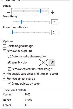
We have 13 grouped objects with a total of 1085 curve objects. That's waayyy too many.
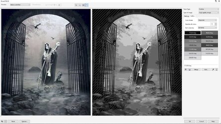
So we OK, the PowerTrace, and SHAZZAAAMMM.
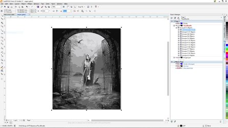
In the end it should be one curve object/path per layer per shade. Otherwise the laser/software can't cope.
What we do now is create empty layers with the name of the shade, and copy the appropriate group to the layer and ungroup.
You can check the groups gray scale value in object properties.
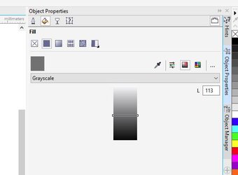
So each layer should end up with the contents of the original group and look like this...
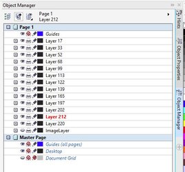
Now in a perfect world, we would select all the curves from each layer and "combine", but we cant do that yet...
We need to go through and simplify/merge more colors. This is where the busy work comes in, but is waaay easier now that we used the preprocessing merge technique...
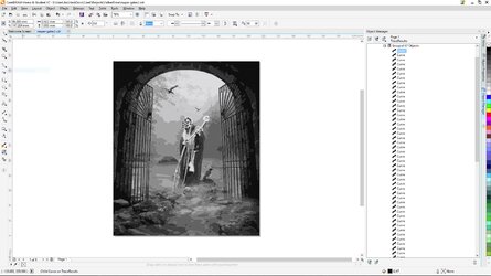
Also we are going to eventually delete the 17 layer as it is the darkest, and will be the areas that don't get etched.
But we need to start by changing 17's, we don't want to be deleted, to 33's and copied to that layer.
We use the color eyedropper tool to identify the color we want to merge to, and then click all the object we want that color, then use "Move to layer.." tool.
I am not going to get into the total specific of what/why you merge or not. The biggest goal being maintaining detail, while simplifying
Here is an example of what we look at up closer
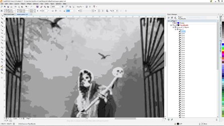
I can't just delete it. As then it becomes a hole and black anyway
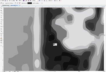
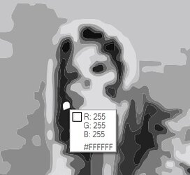
So we user the dropper/fill tool
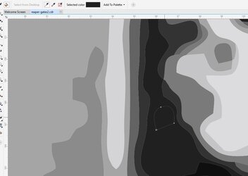
And now they match! Those two objects will merge when we run a "combine" on the layer.
For now we just leave it and it provides a edit crumb trail for us.
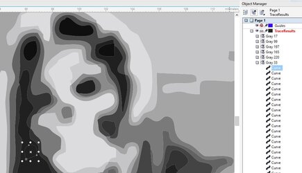
Ok, that's it up to here. I have some edit time to go through the entire image.
In part 3 we'll go through what I learned and review the final product.
Tots Zien
EDIT:
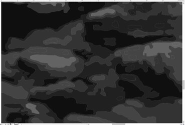
So I spent a few this morning working on an area:
You can see all the edit crumbs, being the circle areas that are the same shade as their containing object.
These are the edits I have made so far. Going through this section took about 15 minutes...
Last edited:
- Joined
- Sep 7, 2013
Under a minute to load up the page Swart!
HIT ME WITH SOME BIG PICS! That'll choke me out!
Basically, when you posts pics of the front case panel all done up, it'll take 10min to load.
Thanks for the write up too! Long process I must say, good thing you have all that patience you built up in the OCF daycare eh?
Just occurred to me today too that Winter is just around the corner to eh? Pretty soon them polar bears will be out roaming the streets again!
HIT ME WITH SOME BIG PICS! That'll choke me out!

Basically, when you posts pics of the front case panel all done up, it'll take 10min to load.
Thanks for the write up too! Long process I must say, good thing you have all that patience you built up in the OCF daycare eh?

Just occurred to me today too that Winter is just around the corner to eh? Pretty soon them polar bears will be out roaming the streets again!

Just occurred to me today too that Winter is just around the corner to eh?
Time to stock the freezer with frozen peas.
- Joined
- Sep 13, 2015
Time to stock the freezer with frozen peas.
I still say tomatoes are the way to go due to the high water content leading to a higher specific heat as compared to peas

- Joined
- Apr 3, 2015
- Location
- Planet Earth
- Thread Starter
- #87
Silver_Pharaoh said:HIT ME WITH SOME BIG PICS! ... Winter is just around the corner to eh..
Huh, I usually resize screenshots down to ~1024/768, but left these 1920 to show higher detail...
I just think you had a good interwebz connection, no birds where sitting on the wire....
Funny you bring up winter, although comes around sooner in TGWN...
Over the last week, the crickets have started up at night, really early too. Need to check the farmers almanac.
And the hot nights have given way to the crisp taste of fall in the night air...
Last winter was not so great for Utah standards.
Alta got a total of 438.5" snow which was calculated to ~38" water/rain.
Usually we should be around +500" total snowfall.
No Polar Bears

Blaylock said:Time to stock the freezer with frozen peas.
No frozen peas at Lochekey's homestead
Blaylock said:I still say tomatoes ... high water content leading to a higher specific heat as compared to peas
Tomatoes!? You freeze a tomato and what???...

So, definitely taking advantage of winter this year. Especially with The Bianch.
Just need to get everything prepped to run cold.
Salud
- Joined
- Apr 3, 2015
- Location
- Planet Earth
- Thread Starter
- #88
Y oh Wye oh waɪ oh Why?
Ok, it took two months to get back to this cabling project...
But as I previously mentioned, I knew if I just plugged in the stock cables to fire it up it would be awhile till I got back around to it.
In the meantime I did manage a few sub's here and there. The best effort being:
http://hwbot.org/submission/3275086_swarthack_memory_clock_ddr4_sdram_2080.2_mhz
So I've covered the whole PWM splitter topic before, but it took on a new beast mode and attacked.

Mostly in the form of shiaty cables. In short I basically had to redo all the factory double crimps.
And then I ran out of male pins!!! They started giving out as I was cramming them around, bending and routing.
I tend to get a little aggressive when bunching, sleeving and routing. And have had to go back numerous times and fix things.
I my mind it exposes the weak links, which usually are factory. SwartHack make solid crimps!
This did allow me to replace some 4x connectors with 3x's.
This is a correctly re-wired 3 fan -> 1 PWM hub connector.

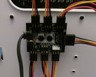
Let’s not even get into the discussion of PWM hubs right now and how to make them work correctly,
Or the fact you can get “4 wire PWM splitters” that do not work correctly...
So here we go with some sleeving, of sorts...
Let me be the first to say I am not 100% pleased with my efforts, especially the pregnant and kinda odd sleeving


I went through hours thinking it all out and measuring for offsets so connectors would not be coincident and everything would sleeve all sleek and cool...
Hardy Har, I got some really odd results, because in my fit of re-pinning all the connectors everything seemed to end up coincident!!
And I wasn't about to go all clipping and re-pinning at this point.


Besides I knew that from what I learned, how I would do it much better on a re-do, which will be pending down the road...
So tidied up/combined the rad fans accordingly...


What’s going on here?!?!

One of my “Master Plan” Y's just wasn't quite working out…
The problem here being the white port on PWM hub CAN NOT be a splitter.
This is the primary device all others are controlled by.
I set the lower CPU radiator interior in-fan, which also conveniently blows right onto the CPU loop pump and is visible.
In the end I junked the shorty after a few re-pinnings and just threw on a full length rig that survived the massacre.

So, after all that...
So the 14 rad fans are all set, more or less…
I still have the 4 case fans, but those will be no-brainer.
Currently getting back at the custom PSU cables, gonna knock those out here…
Tots Zien
Ok, it took two months to get back to this cabling project...
But as I previously mentioned, I knew if I just plugged in the stock cables to fire it up it would be awhile till I got back around to it.
In the meantime I did manage a few sub's here and there. The best effort being:
http://hwbot.org/submission/3275086_swarthack_memory_clock_ddr4_sdram_2080.2_mhz
So I've covered the whole PWM splitter topic before, but it took on a new beast mode and attacked.
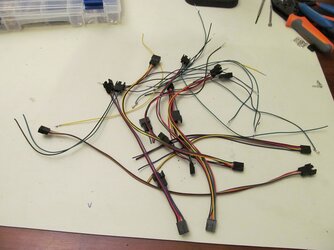
Mostly in the form of shiaty cables. In short I basically had to redo all the factory double crimps.
And then I ran out of male pins!!! They started giving out as I was cramming them around, bending and routing.
I tend to get a little aggressive when bunching, sleeving and routing. And have had to go back numerous times and fix things.
I my mind it exposes the weak links, which usually are factory. SwartHack make solid crimps!
This did allow me to replace some 4x connectors with 3x's.
This is a correctly re-wired 3 fan -> 1 PWM hub connector.
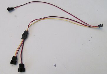
Let’s not even get into the discussion of PWM hubs right now and how to make them work correctly,
Or the fact you can get “4 wire PWM splitters” that do not work correctly...
So here we go with some sleeving, of sorts...
Let me be the first to say I am not 100% pleased with my efforts, especially the pregnant and kinda odd sleeving
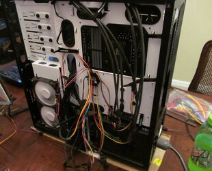
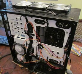
I went through hours thinking it all out and measuring for offsets so connectors would not be coincident and everything would sleeve all sleek and cool...
Hardy Har, I got some really odd results, because in my fit of re-pinning all the connectors everything seemed to end up coincident!!
And I wasn't about to go all clipping and re-pinning at this point.
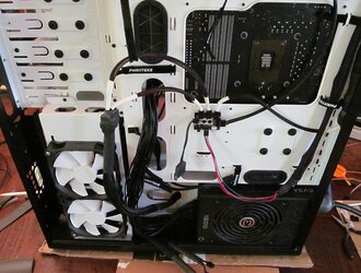
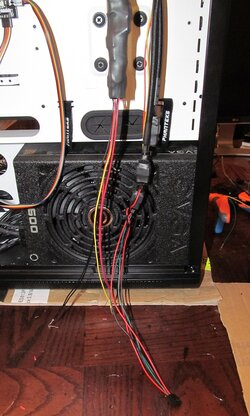
Besides I knew that from what I learned, how I would do it much better on a re-do, which will be pending down the road...
So tidied up/combined the rad fans accordingly...
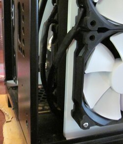
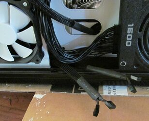
What’s going on here?!?!
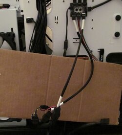
One of my “Master Plan” Y's just wasn't quite working out…
The problem here being the white port on PWM hub CAN NOT be a splitter.
This is the primary device all others are controlled by.
I set the lower CPU radiator interior in-fan, which also conveniently blows right onto the CPU loop pump and is visible.
In the end I junked the shorty after a few re-pinnings and just threw on a full length rig that survived the massacre.
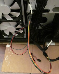
So, after all that...
So the 14 rad fans are all set, more or less…
I still have the 4 case fans, but those will be no-brainer.
Currently getting back at the custom PSU cables, gonna knock those out here…
Tots Zien
- Joined
- Sep 7, 2013
Eh! Glad to see ya back eh? 
Looks much neater than before Swart nice!
Nice job on the DDR4 sub to eh!
Oh and the page loaded fine but man was it laggy to scroll to the bottom of the page to type this!!
Looks much neater than before Swart nice!
Nice job on the DDR4 sub to eh!

Oh and the page loaded fine but man was it laggy to scroll to the bottom of the page to type this!!
- Joined
- Apr 3, 2015
- Location
- Planet Earth
- Thread Starter
- #90
SP said:Eh! Glad to see ya back eh? ...
kay, thanks, How's the climbit in the GWN, eh?
Don't sleep on my other proj logs hoser (sig)
The Bianch is getting exciting...
Salud
- Joined
- Sep 7, 2013
kay, thanks, How's the climbit in the GWN, eh?
Don't sleep on my other proj logs hoser (sig)
The Bianch is getting exciting...
Salud
Nooooooo00!
My poor interwebz!!
I couldn't even load this page to add this reply because of the bianch log!
The weather her is nice today eh? Perfect for fixing brake calipers.
my god this internet really does suck lol
- Joined
- Apr 3, 2015
- Location
- Planet Earth
- Thread Starter
- #92
Cable fit dry run
So dang dilly hole, I had hoped to get this done before I got the parts to finish upgrading The Bianch (sig.), which arrived yesterday.
I almost made it, but still have some work left.
Lots of lesson's learned through this whole custom cabling process. Some of which I will elaborate on later, including the cable combs I used...
But here are the preliminary results:


I know it would have been a lot easier to have returned the cables instead of re-pinning them, buuuuut,
I had to have those colors and was anxious to proceed...
Need to pull and re-route the GPU cables a bit and fix/check the connection, one popped during the fitting.

Here is the final approach I took, separate cables without pig-tails

Sooo, next time, not sure what I will do.
Depends on the project and how it "feeeels".
I do know if you use the cables as is, e.g. CPU and mobo; and utilize the extension/cross-over cables, they are pretty dreamy to work with.


Except my mobo 5x2 + 9x2 PSU connection -> 12x2 mobo connection abomination-creation.

Which was finally some clarity of thought actually over the aborted "shorty" madness.
Will make a new cleaner one, using this model to measure the required lengths for each connection.
Key feature though, the 5x2 portion can swing to either side!!!
PHHHzzzz CrKlll ZoZT AAAAANNNNNNCCCCCCHHHHHHH
**********WE INTERRUPT THIS POST FOR AN URGENT MESSAGE FROM THE NSR BROADCAST SYSTEM********************
**********END OF MESSAGE*****WE NOW RETURN TO THE IRREGULARLY SCHEDULED POST*****************
AAAAANNNNNNCCCCCCHHHHHHH PHHHzzzz CrKlll ZoZT
But I got a little carried away with the soldering iron trying to "trim" some fray, which I don't advise, obviously
I actually finally fingured out to use the soldering iron to cut/trim before hand.

Pick a Tool, Any Tool...

Gonna get these cables pulled and back in, then fire him up!!!
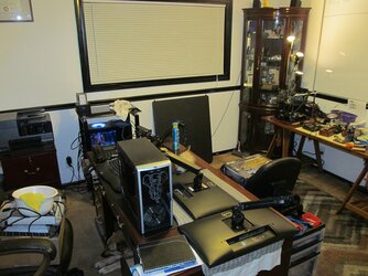
and then finally move the rig from my "Dining Room Table" to the Orafice.
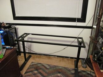
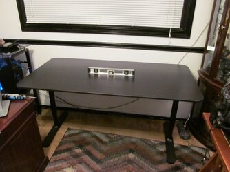
Got a new table upgrade to house the rig!
Fingers crossed...
Hasta Entonces
So dang dilly hole, I had hoped to get this done before I got the parts to finish upgrading The Bianch (sig.), which arrived yesterday.
I almost made it, but still have some work left.
Lots of lesson's learned through this whole custom cabling process. Some of which I will elaborate on later, including the cable combs I used...
But here are the preliminary results:
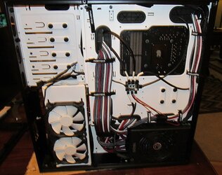
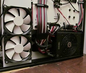
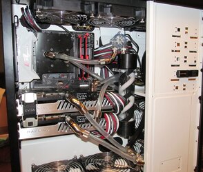
I know it would have been a lot easier to have returned the cables instead of re-pinning them, buuuuut,
I had to have those colors and was anxious to proceed...
Need to pull and re-route the GPU cables a bit and fix/check the connection, one popped during the fitting.
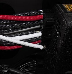
Here is the final approach I took, separate cables without pig-tails
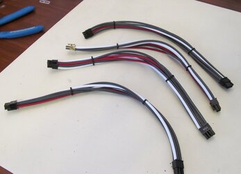
Sooo, next time, not sure what I will do.
Depends on the project and how it "feeeels".
I do know if you use the cables as is, e.g. CPU and mobo; and utilize the extension/cross-over cables, they are pretty dreamy to work with.
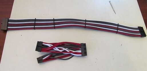
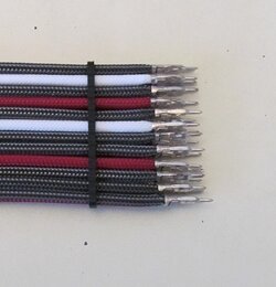
Except my mobo 5x2 + 9x2 PSU connection -> 12x2 mobo connection abomination-creation.
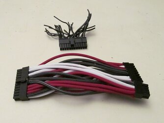
Which was finally some clarity of thought actually over the aborted "shorty" madness.
Will make a new cleaner one, using this model to measure the required lengths for each connection.
Key feature though, the 5x2 portion can swing to either side!!!
PHHHzzzz CrKlll ZoZT AAAAANNNNNNCCCCCCHHHHHHH
**********WE INTERRUPT THIS POST FOR AN URGENT MESSAGE FROM THE NSR BROADCAST SYSTEM********************
AAAAANNNNNNCCCCCCHHHHHHH PHHHzzzz CrKlll ZoZT
But I got a little carried away with the soldering iron trying to "trim" some fray, which I don't advise, obviously
I actually finally fingured out to use the soldering iron to cut/trim before hand.
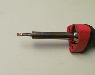
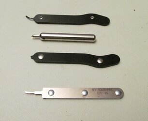
Pick a Tool, Any Tool...
Gonna get these cables pulled and back in, then fire him up!!!
and then finally move the rig from my "Dining Room Table" to the Orafice.
Got a new table upgrade to house the rig!
Fingers crossed...
Hasta Entonces
- Joined
- Apr 3, 2015
- Location
- Planet Earth
- Thread Starter
- #94
The Big Move
Nice segway Sharangir - German's don't say mate, and I guess another poor displaced Irish sod cutter, possibly...
At least one of Her Majesty's loyal subjects..
What happened to Acce55 anyone!?!
He was one of you, but stranded on Royal land, Manchester I believe...
I forgot to link in this post/question that I outsourced...

 www.overclockers.com
Uh, yeah not sure why the mobo adapters have to be such a cluster farck.
There are 3 double crimps on the 24 pin, for what exact reason those specific pinds require that...
Is a question for somebody else. I personally and done with that maddness, for now
So I pulled the GPU cables and gave them a good twice-over.
Besides fixing the ones that popped (3), I replaced a number of suspect crimps.


And I also added some more cable combs, which butt right up against the connector, for support and hides and "issues".


And on the cable combs. They are the only combs I will ever use again! Well, at least that style.
I have only seen them at this place, which I have pimped before:
http://www.ensourced.net/
Check his website right now, "No new orders while I catch up".
This guy also offers a "shorty" adapter for the mobo. I shot him an message asking about one for an EVGA SUperNova.
His response was simply, "..he was not familiar with them."
So I responded with the pinout specs and indicated that they could be possibly the same or very similar, and that I would be his first customer and guinea pig." ... No reply...
Oh well, I wish him luck and I hope I can get more combs from him when I need them.
I order a pretty good grip of them and he threw in a bunch of samples.
I haven't checked out that Nils character yet... maybe he has something similar??
Did I mention I got a new table and have finally moved Father Time from the "dining room" to my office, after more than a year!

Hold onto that mouse tight, because now we are moving into two new exciting phases of this project!!!
It's so exciting!!!
Tots Zien
Nice segway Sharangir
At least one of Her Majesty's loyal subjects..
What happened to Acce55 anyone!?!
He was one of you, but stranded on Royal land, Manchester I believe...
I forgot to link in this post/question that I outsourced...
Wiring up Dual 980ti Hydro Copper 8x6 pin connections
So I find myself on the precipice of absolute greatness or utter failure... I have decided, with some prodding by Lochekey, to make my own cables, kinda, for Father Time. (sig.) ( I got a bunch of the individually pre-sleeved wires) So it should be pretty easy and straight forward, except where...
Uh, yeah not sure why the mobo adapters have to be such a cluster farck.
There are 3 double crimps on the 24 pin, for what exact reason those specific pinds require that...
Is a question for somebody else. I personally and done with that maddness, for now

So I pulled the GPU cables and gave them a good twice-over.
Besides fixing the ones that popped (3), I replaced a number of suspect crimps.
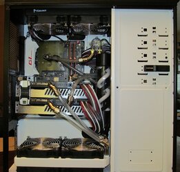
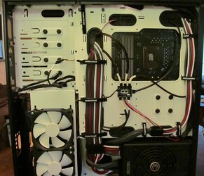
And I also added some more cable combs, which butt right up against the connector, for support and hides and "issues".
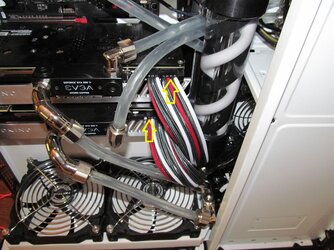
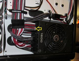
And on the cable combs. They are the only combs I will ever use again! Well, at least that style.
I have only seen them at this place, which I have pimped before:
http://www.ensourced.net/
Check his website right now, "No new orders while I catch up".
This guy also offers a "shorty" adapter for the mobo. I shot him an message asking about one for an EVGA SUperNova.
His response was simply, "..he was not familiar with them."
So I responded with the pinout specs and indicated that they could be possibly the same or very similar, and that I would be his first customer and guinea pig." ... No reply...
Oh well, I wish him luck and I hope I can get more combs from him when I need them.
I order a pretty good grip of them and he threw in a bunch of samples.
I haven't checked out that Nils character yet... maybe he has something similar??
Did I mention I got a new table and have finally moved Father Time from the "dining room" to my office, after more than a year!
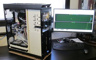
Hold onto that mouse tight, because now we are moving into two new exciting phases of this project!!!
It's so exciting!!!

Tots Zien
- Joined
- Apr 3, 2015
- Location
- Planet Earth
- Thread Starter
- #95
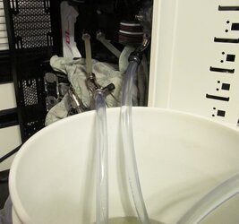
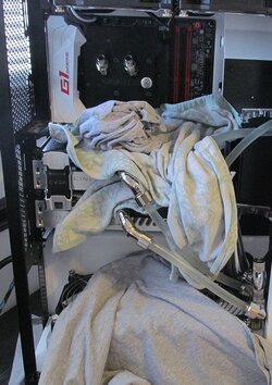
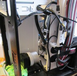
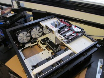
IT'S A MASSACRE!!!!
So I read my last post, and am like arrgghh!!!!
I have been very negligent in working on this rig, other than running/benching it (open case though...)
So it that essence it's alright, but I have developed a bit of an infection....
And I needed to tear-down anyway, I have some rad filters coming...
And there was a lot to desire on my set-up after running it awhile, so can reflect on that while I re-build...
But man, with "Buck Rogers" (sig.) down and getting serviced I am getting lean on set-ups...
EDIT:
Farming this one out to cooling forum for any feedback...
See:
http://www.overclockers.com/forums/...-HUZAH-WHAAA!!-Got-an-infection-in-both-loops!!!
for the discussion...


Luego
So I read my last post, and am like arrgghh!!!!
I have been very negligent in working on this rig, other than running/benching it (open case though...)
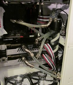
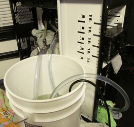
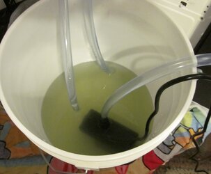
So it that essence it's alright, but I have developed a bit of an infection....
And I needed to tear-down anyway, I have some rad filters coming...
And there was a lot to desire on my set-up after running it awhile, so can reflect on that while I re-build...
But man, with "Buck Rogers" (sig.) down and getting serviced I am getting lean on set-ups...
EDIT:
Farming this one out to cooling forum for any feedback...
See:
http://www.overclockers.com/forums/...-HUZAH-WHAAA!!-Got-an-infection-in-both-loops!!!
for the discussion...
Luego
Last edited:
- Joined
- Apr 3, 2015
- Location
- Planet Earth
- Thread Starter
- #96
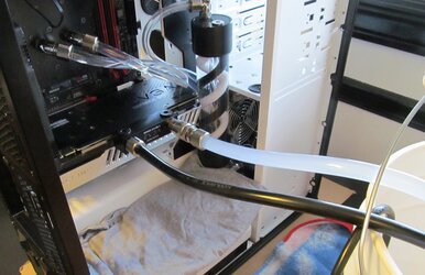
Father Time slowly coming of age
So thanks to all those that chimed in from: http://www.overclockers.com/forums/...-HUZAH-WHAAA!!-Got-an-infection-in-both-loops
Will post an update there on what I learned ...
As previously stated, the "infection" caused me to step back and take to this project build again instead of just benching the rig open case...
There is too much here and to come to stay in a box...
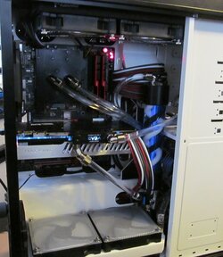
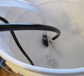
So ripped everything down, cleaned and did a reverse job on my routes. Now pumping right to blocks.
I also ditched the two way gCard route and am going with a cross-over connection.
Sticking with one card for now while I work on front panel connections, etc...
gCard Enema...


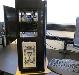
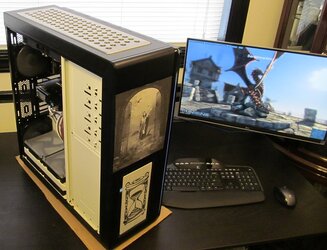
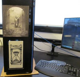
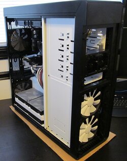
Looking handsome with some paneling on finally...


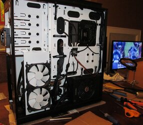
Getting the front and back case fans in finally...
Used this mesh from home depot to make a custom screen.
I literally needed the 2mm..


Gonna use some of that screen to build a cover that fits the entire area...


This stuff really bummed me out. If I did not have "Skills" what would an everyday hack do???!!
These connections are bumpkin!!!
Watch the SwartHack Majic...
This was the power switch...


Ended up fixing both sides...


HD LED the same, haven't fixed this one yet...

And that's just the beginning of the changes, more graphics/artwork, extreme lighting white/black and the long awaited Crystal Fonts LCD display, with a number of suprises...
Hang tight everyone!!!!
Cheers!
So thanks to all those that chimed in from: http://www.overclockers.com/forums/...-HUZAH-WHAAA!!-Got-an-infection-in-both-loops
Will post an update there on what I learned ...
As previously stated, the "infection" caused me to step back and take to this project build again instead of just benching the rig open case...
There is too much here and to come to stay in a box...
So ripped everything down, cleaned and did a reverse job on my routes. Now pumping right to blocks.
I also ditched the two way gCard route and am going with a cross-over connection.
Sticking with one card for now while I work on front panel connections, etc...
gCard Enema...
Looking handsome with some paneling on finally...
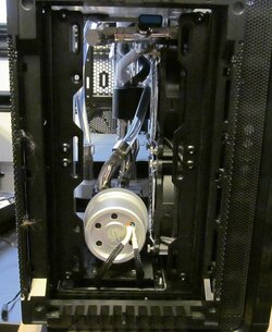
Getting the front and back case fans in finally...
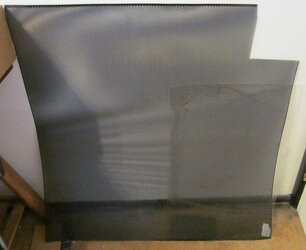
Used this mesh from home depot to make a custom screen.
I literally needed the 2mm..
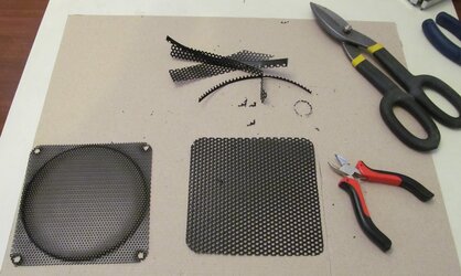
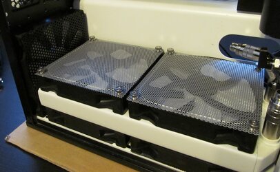
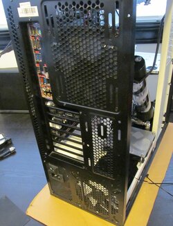
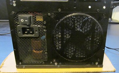
Gonna use some of that screen to build a cover that fits the entire area...
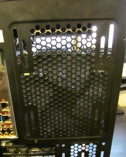
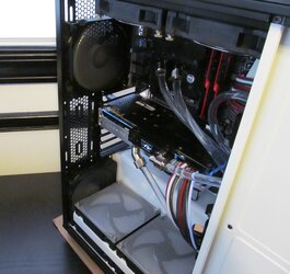
This stuff really bummed me out. If I did not have "Skills" what would an everyday hack do???!!
These connections are bumpkin!!!
Watch the SwartHack Majic...
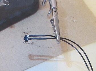
This was the power switch...
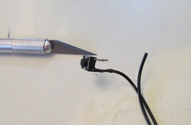
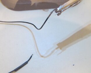
Ended up fixing both sides...
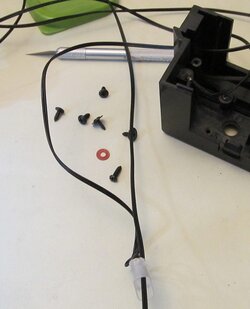
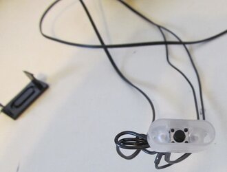
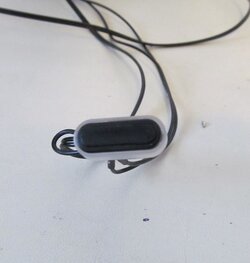
HD LED the same, haven't fixed this one yet...
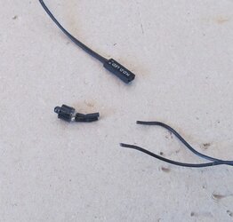
And that's just the beginning of the changes, more graphics/artwork, extreme lighting white/black and the long awaited Crystal Fonts LCD display, with a number of suprises...
Hang tight everyone!!!!
Cheers!
- Joined
- Sep 7, 2013
Hang tight? I already am. You and you damn pictures swart!!! 
I really should put some grilles on my fans as well. Should keep the dust way down!
I really should put some grilles on my fans as well. Should keep the dust way down!
Very nice update.
As always Mr. Hack I have a question for you. I guess I'm that student that sits at the back of the class that always raises his hand after each lesson. LOL
Why dust filters on your exhaust fans? Wouldn't that just keep the dust in the case and make it difficult to clean?
Just my never ending curiosity at work here, no criticism.
- Joined
- Apr 3, 2015
- Location
- Planet Earth
- Thread Starter
- #100
Filter pic
My esteemed mentor, I not only desire your feedback, err criticisms, I very much appreciate them...
I am open to all feedback, input, advice and disparaging remarks...
In your case it would be beaver hair...
So yeah, err seems we need to discuss the difference between a "grill" and a "filter".
I had meant to illustrate it, but seem to have neglected to take pics????
Anyway, YES you are right Blaylock, why put filters on "outs", which I in fact did not. Only grills!
I did in fact put filters on all ins: bottom rad, side rad and front fans, you just cant see them...
From this pic, you can see the different filters I used.

These are the ones (as indicated) to go with: http://www.performance-pcs.com/fan-dust-filter-foam-140mm.html
Cant beat the price either
DO NOT get the others. They don't work as in-line filters cause they throw everything of and no pre-made holes.
They are super expensive also.
When I am in process and expose the filters I used I'll snap a pic to illustrate.
Basically go between the outer fan and radiator...
Know the use or over-use of grills and their affects on airflow can be debated ad nausea...
But I have 18 fans, YES 18!!! Count them, so I am really not too worried
I am looking for local, and besides he couldn't do 8-bit grayscale laser etching! (Mode on this is subsequent posts...)
I want the Shapeko set-up with a laser, just can't afford it right now...
https://shop.carbide3d.com/products/shapeoko-xl-kit
Found a kid who may do some air-brushing for me on the interior. He is new, but seems talented...
Thinking about a play on Salvador Dali's Persistence of Memory. You know the melting clocks...
I also want to go full window, which entails modding the stock panel... not too sure on this one yet...
Thanks as always for the feedback and praise. My fragile ego requires it
Cheers
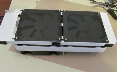
EDIT: here is a pic I stumbled across. This is the bottom of the bottom rad bracket
After this pic, I moved the filters to the other side of the bracket, so they are NOT between rad and fan as I previously stated!!!
I do know I put the filters for the side rad between the rad and fan. I should go and change these...
At .99c a pop, I am just planning on replacing anyway. We'll see how they really do when I put them on The Bianch...

Very nice update.
As always Mr. Hack I have a question for you. I guess I'm that student that sits at the back of the class that always raises his hand after each lesson. LOL
Why dust filters on your exhaust fans? Wouldn't that just keep the dust in the case and make it difficult to clean?
Just my never ending curiosity at work here, no criticism.
My esteemed mentor, I not only desire your feedback, err criticisms, I very much appreciate them...
I am open to all feedback, input, advice and disparaging remarks...
Yeah, my problem is dog hair as well, it gets inside the radiator fins and it impossible to get out.SP said:I really should put some grilles on my fans as well.
In your case it would be beaver hair...
So yeah, err seems we need to discuss the difference between a "grill" and a "filter".
I had meant to illustrate it, but seem to have neglected to take pics????
Anyway, YES you are right Blaylock, why put filters on "outs", which I in fact did not. Only grills!
I did in fact put filters on all ins: bottom rad, side rad and front fans, you just cant see them...
From this pic, you can see the different filters I used.
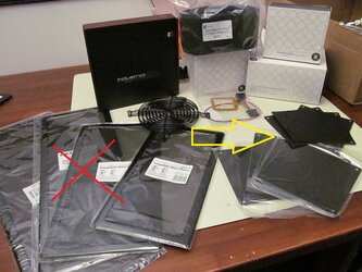
These are the ones (as indicated) to go with: http://www.performance-pcs.com/fan-dust-filter-foam-140mm.html
Cant beat the price either
DO NOT get the others. They don't work as in-line filters cause they throw everything of and no pre-made holes.
They are super expensive also.
When I am in process and expose the filters I used I'll snap a pic to illustrate.
Basically go between the outer fan and radiator...
Know the use or over-use of grills and their affects on airflow can be debated ad nausea...
But I have 18 fans, YES 18!!! Count them, so I am really not too worried
Thanks- and more to come eventually. I have been sleeping on it as the guy who did the hour glass is in Wisconsin...Lochekey said:Love the graphics Swart.
I am looking for local, and besides he couldn't do 8-bit grayscale laser etching! (Mode on this is subsequent posts...)
I want the Shapeko set-up with a laser, just can't afford it right now...
https://shop.carbide3d.com/products/shapeoko-xl-kit
Found a kid who may do some air-brushing for me on the interior. He is new, but seems talented...
Thinking about a play on Salvador Dali's Persistence of Memory. You know the melting clocks...
I also want to go full window, which entails modding the stock panel... not too sure on this one yet...
Thanks as always for the feedback and praise. My fragile ego requires it
Cheers
EDIT: here is a pic I stumbled across. This is the bottom of the bottom rad bracket
After this pic, I moved the filters to the other side of the bracket, so they are NOT between rad and fan as I previously stated!!!
I do know I put the filters for the side rad between the rad and fan. I should go and change these...
At .99c a pop, I am just planning on replacing anyway. We'll see how they really do when I put them on The Bianch...
Last edited:
Similar threads
- Replies
- 80
- Views
- 4K
- Replies
- 6
- Views
- 546
