• Welcome to Overclockers Forums! Join us to reply in threads, receive reduced ads, and to customize your site experience!

'DownUnder' Build Thread - Déjà vu

Overclockers is supported by our readers. When you click a link to make a purchase, we may earn a commission. Learn More.

Flat-6

Member
Joined
Jan 30, 2015
Location
Australia
Yeh I know most of you folks have seen it all before...:cool:

Here is another Caselabs SMA8 build but with a slight twist here and there.

It is my first acrylic build but certainly not my first WC endeavour. Hopefully it will look a tad more professional as compared to my first foray into watercooling from many years ago (circa early 90's - back in the Intel P2 & P3 era).

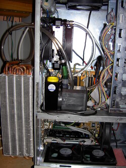
Here was that attempt - Worked pretty well for a number of years and it survived a number of upgrades during its reign...! Built in an old steel server case which was extremely heavy...ahh they were the days.. :)

PICT0051.JPG


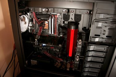
Back in June/July 2014 the WC bug bit again so I built a reasonably simple setup within a Corsair 900D. Single loop and was constructed from Primochill Advanced LRT with Bitspower fittings.

Here is a quick pic - It is my current rig and has been very reliable to date. 4790K running at 4.8Ghz [Cache @ 4.6Ghz] kitted out with an overvolted and overclocked EVGA 780Ti Classified - Main WC gear consists of a Swiftec MCP35X2, XSPC Photon and Alphacool rads all managed via an Aquaero 6XT.


2014_PC.jpg


So now I want to dabble with acrylic tubing so I decided on a Caselabs SMA8 build. I chose this case due to its similarities (form factor) with my Corsair 900D which I like.

As the SMA8 is quite roomy in some respects - I wanted to fill up the space to the right of the mobo with two reservoirs and whatever else. Since building my 900D, I also wanted to include a visual flowmeter - in particular an industrial rotameter styled flowmeter. Not for any technical reasons but more so as a bit of a talking point and the fact that I have not seen a build with one...!

I have not decided on any of the PC electronics hardware at this stage. I want to design my loop first and design it with some longevity/flexibility & overkill in mind so that just about any hardware config (within reason) can be added at any time once the loop is complete. I want to design the loop around the case more so than designing it around the actual electronic PC hardware as much as I can. I would prefer an end result whereby I can upgrade the PC electronics with minimal WC loop changes required. This should provide me with the best flexibility and return on investment (if you can call it that...:p) over the life of the case and the expensive watercooling bits.

NOTE: I am not a fan of the look of bent tubing and I much prefer the more mechanical/muscular look of straight tubing combined with fittings when it comes to bends. While its easier to build in some respects (and more difficult in others) it is definitely way more expensive to go this way (many more fittings required). You can also run out of space in tight areas real quick as you need to allow for extra clearance for various fittings which may not be utilised if bending acrylic..


Here are some of the major components which I have already purchased and will be part of the build:

Case: Caselabs SMA8 (**maybe optioning it out with a pedestal - undecided on this as yet)
Reservoir: XSPC 270 Photons x2 - Connected in parallel
Radiators: Alphacool UT60 560 (Bottom) & Alphacool XT45 560 (Top - will require case mod). If I decide on the pedestal I will add another UT60 560 in the bottom.
Pumps and Top: D5 x2 matched to EK Dual Top for serial connection of pumps.
WC/Fan Controller: Aquaero 6XT - Coolant Flow to be monitored with MPS400 sensor.
Fittings: Bitspower Silver Shining utilised throughout build. 16mm Bitspower hardline/acrylic dual O-ring tubing compression style fittings for mating to acrylic tube.
Tubing: Bitspower 16mm OD acrylic.
Fans: TBA (Undecided at this stage but will be selecting 140mm variants).


Lets get started...!


As I want to keep the loop design simple & flexible I chose to opt for a single loop solution - However I really like a dual res setup for asthetics.

So I decided on connecting two reservoirs in parallel operation.

One advantage to this is that restriction is cut in half for the reservoirs, however the drawbacks are the extra fittings (cost) and a much more complex configuration for tubing routing.

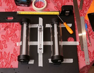
Below is a pic from the other day when I just started to mark out my lines/positions for drilling etc.


Mounting Reservoirs.JPG


Today I spent some time mounting the reservoirs and also playing with the acrylic tubing. The acrylic tubing itself is very cheap as compared to flexible tubing so no need to be worried if you end up making mistakes (cutting too short and the like).

There is a bit of a learning curve when it comes to cutting the tubing to the exact (correct) length. One needs to ensure that the tubing is cut with some clearance in mind to allow you to install & adjust the fittings for an exact parallel/square fit so that the tubing runs end up exactly square. You really need the acrylic tube to 'float' a little between its fittings rather than being hard up right against their ends while, at the same time being careful that the tubing is NOT cut too short which can prevent both o-rings from sealing correctly....!

Overall it did not take too long to get the hang of it. Tubing ends need to be chamferred and silicone grease applied to the o-rings for ease of fitment to the Bitspower fittings.


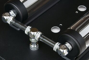
Top of reservoirs - Fill/Bleed ports are combined for parallel setup. Note pass-through connection through rear panel.

Tubing01.JPG


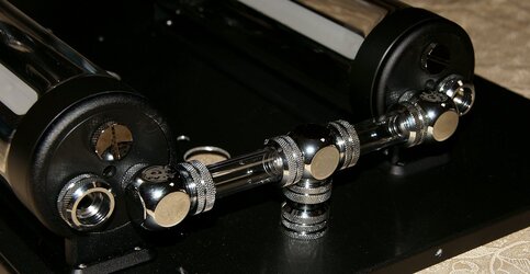
Bottom of reservoirs - Inlets joined together and passed through to the rear of the case via a pass-through fitting.

I have not finalised the outputs from the reservoirs as I am waiting on some fittings to come in. Should have them here on Monday. I will also need to assemble part of the case to measure out the exact location for the combined res output tube which needs to run through the mid plate for connection to the pumps.

Tubing02.JPG


More to come soon.....!!!
 
Last edited:
Spent a bit of time on my build this weekend, predominately modding the SMA8 case.

The SMA8 is designed for a 480 rad up top, however the SMA8 has quite a bit of width inside the main motherboard chamber. I was tempted before I purchased the SMA8 to fit a 560 rad up top as I had seen one other person perform this modification.

A 560 rad has a lot more surface area than the more common 480 sized rad and I was keen to take advantage of the SMA's width and squeeze in a 560 up top.


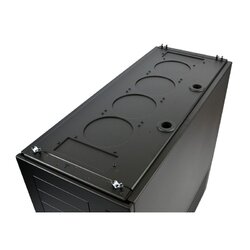
Here is the stock top deck arrangement - Note that the case comes with blank covers as standard. A 480 rad just simply bolts in once the blanks are removed - easy as, with a 560 though you are out of luck...:cry:

SMA8 Stock Top rad_fan mount.jpg


So just to be different I decided to opt for a 560 up top with the proviso that I had to cut into my shiny new Caselabs case...:shock:

I spent quite a few hours on this and the majority of time was simply taking measurements off my rad and then accurately transferring these to the case in preparation for cutting and drilling. I made sure that I measured at least 3x before starting any cutting and drilling...:D

One of the issues was that I could not find any templates that matched Alphacool's rad dimensions. I did email Alphacool direct and they were kind enough to send me their drawings which helped to confirm my measurements but a ready to go template would have made it much easier.

One needs to be careful as Alphacool rads have some different dimensions for their mounting holes etc - eg: 16mm fan spacing (other brands tend to use 15mm), and 124.5mm fan hole spacing rather than being 125mm exact.

Cutting was done using a jigsaw traversing up against a clamped straight edge to ensure the cuts were dead straight and parallel with the case etc.

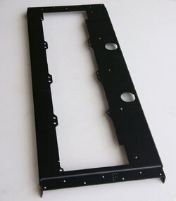
Finally ended up with this....


SMA8 Top Case 560 Rad Cutout Mod.jpg


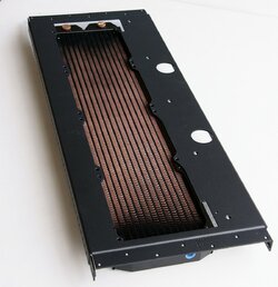
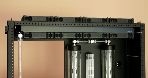
...and here is my Alphacool XT45 56 rad just loosely positioned under the lid so you can get an approximate idea of how it will look when fully mounted. Three mounting locations for the rad are left unused due to the original cutouts in the top, however these will not be an issue as the rad will be more than secure with the remaining attachment points.

Top 560 Rad_A.jpg


You will note that the rad is offset from the centre, this is in part due to the extra width of the 560 Vs the 480. We still require space between the rad and the motherboard tray for a few cables etc. The 560 rad mounts along the same edge (motherboard side) as the 480 would, therefore the wider 560 rad simply extends further towards the window side of the case.


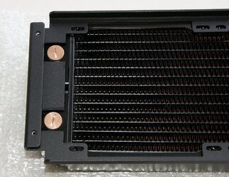
I also noted another issue with the side rad mount which required some attention. When trial fitting my rads I noted that two (spare) port stop fittings on my Alphacool 560 rads would foul on the optional rad mounts. Users may opt to space out the rad a touch as it only fouls by a few mm however (depending on wiring routes) I may wish to access these ports for a temp sensor etc. I ending up quickly filing a clearance space for these two ports for a more user friendly/flexible setup.


SMA8 Modified Rad Side Mount.JPG


Took advantage of PPC's Halloween discount code last week so I ordered a heap more Bitspower fittings for the rig which should hopefully be here by mid week - Did I mention that this rig requires lots of fittings...:bang head
 
Last edited:
Modded my XSPC Photon 270 reservoirs today...

If you would like further detail on this modification, head over over to my detailed mod thread over here: http://www.overclockers.com/forums/...-XSPC-Photon-Modification-Improving-the-breed


Not sure of which colour option to go for as far as the Aquapipe is concerned - What do you guys think, Black or Silver Shining???? Leaning towards the Silver myself but have not fully decided as yet.


Here is my Photon 170 test reservoir fitted with a black Aquapipe.

uUOFpd.jpg


One of my Photon 270's which I modded today with a Silver Shining Aquapipe.

cWBfNC.jpg
 
Last edited:
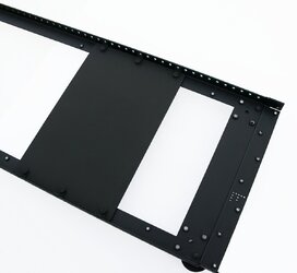
Bottom pump mounting plate for SMA8 series:

My SMA8 case has a large cutout on the bottom - mainly to facilitate easy bottom access for the water cooling components, especially if a solid mid-plate is utilised. The cutout is normally covered with a large coverplate and this is easily removable to gain access to the bottom chamber from underneath if required for loop maintenance etc

The bottom cover plate is quite thin and I guess not all that suitable for mounting heavy pump assemblies etc directly to this plate. I can just see it vibrating etc due to its thin profile and minimal amount of securing screws. As a cover it works well but for certain it is not really designed to have reasonably heavy items mounted on it.

I note that Caselabs have horizontal and vertical accessory mounts for various cases but they do not seem to have an option for a plate of some sort that you can easily mount large pump assemblies at the very bottom of their cases.


So I came up with this idea:

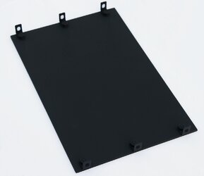
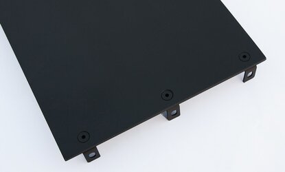
3mm thick Aluminium plate fitted with low profile right angle brackets. The brackets are positioned to line up exactly with the accessory mounting holes along the framework.

The plate can be moved up or down along the length of the case, once in the desired position you can secure the plate with a handful of short 4mm nuts and bolts. As it is low profile it clears any radiators etc with ease and primarily it does not foul with the radiator mounts.

Once secured to the main framework it forms a rock solid assembly which should be able to handle any vibes etc from my pumps - I will be utilising a dual serial D5 EK pump assembly which is quite heavy.

Pump Mount Plate_01.JPG


Small right angle brackets held on with 4mm countersunk hex bolts.

Pump Mount Plate_02.JPG


So now I have a re-positionable heavy duty mount/plate for my pumps....!

Pump Mount Plate_03.JPG
 
Last edited:
I like the black aquapipe, but i feel like the silver one would match better with your fittings.

The quality of work in this buildlog is insane. Subbed, and eagerly awaiting future updates.
 
Thanks...!

Yeh - I decided to go with silver Aquapipes for the very same reason you mention.

I have not posted too much yet as I only just received some more Caselabs options for my case and I was also waiting on a bunch of fittings.

Only gear outstanding at this point is the fans - I think I will go for EK's Varder 140's - Specifically the extended range variant. They only announced them as being back in stock at EK late last week so hopefully my retailer here in Australia receives some stock soon. Once I have the fans I can then fit my rads and start running more tubing between the major parts.
 
Received some parts from Caselabs which I was waiting on and therefore I could progress the build a tad further.

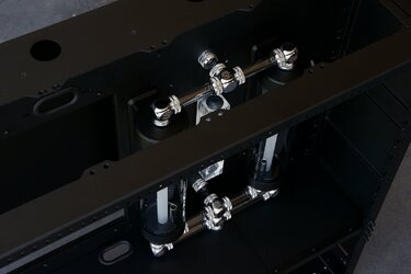
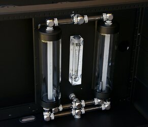
Reservoirs and tubing work connecting both reservoirs completely in parallel is now done....!

The reservoirs and interconnecting tubing has now been pressure tested and this group of components can be considered complete.


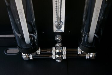
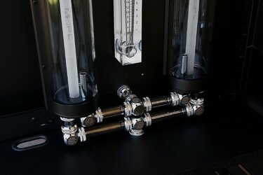
Closeup of the bottom tubing runs.

The lowest run is the outlet from both reservoirs and it routes through a Bitspower pass-through to the lower chamber of the case. this will be connected directly to the input of the pumps.


Resrvoirs Bottom View_a.JPG


Resrvoirs Bottom View_b.JPG


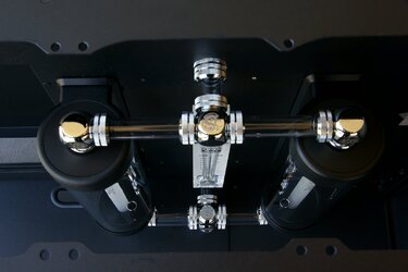
Top Down View......


Resrvoirs Top View.JPG


Angled perspective through 560mm top rad cutout......


Reservoirs Thru Case View.JPG


Overall frontal perspective...........


Reservoirs Complete.JPG
 
Last edited:
Update 20 Dec 2015

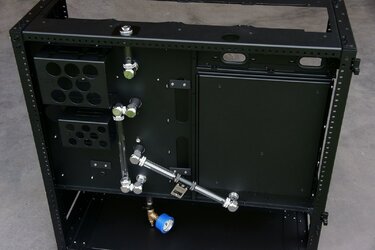
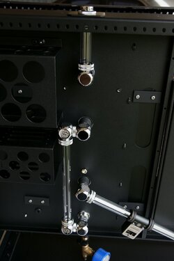
Rear tubing configuration:

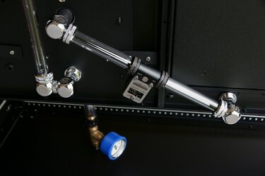
Tubing runs interconnecting Reservoirs, Flow meters [Rotameter & differential pressure type] and Fill port are now complete.

Took a couple of pics for you while pressure testing the complete loop so far. I have been careful to pressure test individual sections & components as the build progresses.

This is to pick up on any tiny air leaks as it can be difficult to trace a very slow leak when the loop is fully complete due to the number of seals/connections involved.


Rear Tubing_b.JPG


Rear Tubing_c.JPG


Closer look at the tubing run for my Aquacomputer MPS400 differential pressure measuring flow meter - This will interface into my Aquaero 6XT controller:

Rear Tubing_d.JPG


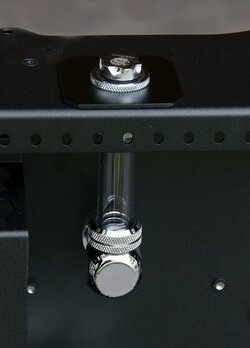
Top Fill Port - Believe it or not, this small section of tubing and its associated components has so far taking me the longest to build.

The tubing just happened to line up with an existing large hole that Caselabs conveniently supply for cables etc.

The hole is way too large for my Bitspower pass-through fitting so I had to knock up some mounting plates for both sides of the case. The pass-through then simply clamps them together. So far so good - However due to the fact that one needs to tighten the collar for the pass-through on the inside face, and the fact that the tubing connects to a Bitspower 90 deg and then to another pass-through on the main back plate of the case [which cannot be moved], there was next to no room to maneouvre the fittings and tubing...!

Had to muck around - stand on one leg, wait for a full moon and the planets to align to get the damn thing to fit. In the end I only just managed to fit it in but I did get it to fit....!

Looks such an easy section to install but it was a PITA - Could have made it a lot easier for myself if the lower 90 degree fitting was a rotary design but it is the weekend and had none on hand.


Rear Tubing_Fill Port.JPG


Rear Tubing_Fill Port_a.JPG
 
Last edited:
I believe rotaries are a must in any platform. Their flexibilities do shine when they're needed.

The build is coming along really nice.
 
Thanks Jack.

In hindsight I should have just removed the front top 'balance' tubing connection on the reservoirs and then loosened the corresponding pass-through which the fill port tubing is ultimately connected to.

A rotary would mean that I would need to make another set of plates as the equivalent rotary type fitting is a tad longer and I would have to shift the whole fill port tube further to the edge of the case. Anyway its done now... :)

Fan mounting next - Wanting to come up with a novel vibration isolating mount for my fans - Ended up selecting Phantek 140 MP type fans so we'll see how I go with those.
 
Last edited:
OK - So I have decided to try out some Phantek PH-F140MP for my fan selection.

It was a toss up between the new EK Varder F3-140ER's and the Phantek MP's. I prefer white blades which will add some contrast to the build and since I am too lazy to paint the Varder blades I opted for the Phanteks.

I'm also going push/pull on all the rads so outright fan performance is not as critical to me as compared to the actual noise fans produce when mounted up against a rad. From the few reviews that I have read both Varders and the Phantek MP range seem to do OK here ie fan noise at mid to low RPMs Vs Actual airflow output through a rad.


One area which many people don't pay much attention to when using fans is vibration isolation. Fans can produce all sorts of vibration components and many of these vibrations can be made worse/amplified simply by hard mounting fans to your case or a rad etc. The rad or case can have vibrations directly transmitted to it and it can simply make noises due to vibes a lot worse.

I have used Noiseblocker fans in my previous build and although not perfect, I liked how they provide a complete package for the isolation of the fan mount for their fans [Basically a number of sleeved grommets and rubber pads fitted to the fan frame].

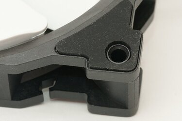
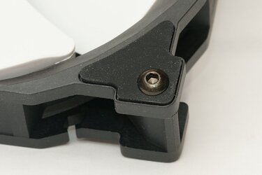
I note that the EK Varder fans do not feature any form of vibration isolation mounting feature and the Phantek MP fans are only designed with a very basic rubber corner pad fitted to their frames:

Fan_a.jpg


While the pad will help somewhat in theory - Its vibration isolating features are soon negated when one places a bolt through the fan frame to mount the fan as the bolt screws onto the hard plastic frames. The bolt simply becomes a direct 'hard' connection from the fan frame directly to your rad/chassis thereby bringing us back to square one ie. the fan is now pretty much 'hard' mounted again...!

Fan_b.jpg


What we need here is some form of isolating mount arrangement - I have seen those rubber/silicone type spikes which can use to mount fans to a chassis however they are not suitable where one uses the fan screws themselves to secure a radiator.


I had thought about this for a few days and came up with the following relatively cheap solution.

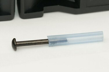
One of my other hobbies is flying large RC helis - With my nitro helis I use silicone fuel line which seemed to be just the perfect solution in providing isolation of the actual fan screws from the fan frames....


I selected the appropriate diameter silicone fuel line [RC Dubro brand 'Large' fuel line size] for my 3mm rad screws [Alphacool rads] and cut the length of the silicone line so that it was around 3mm or so shorter than the shank of the bolt.

Fan_d.jpg


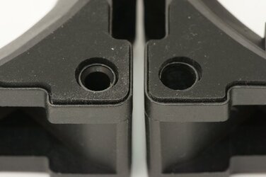
To allow the silicone fuel line to fit loosely in the fan frame - I had to drill out the existing fan mounting holes with a 6.5mm drill bit.

Once done - you can slide the bolt with its silicone sleeve into the fan frame and it should be a loose fit.


Orig fan mount hole on LHS - Approx 4.5 diam from memory - RHS fan hole has been drilled out to 6.5mm

Fan_c.jpg


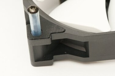
Bolt and its silicone sleeve should just fall in:

Fan_e.jpg


When finally mounting the fan - It is important that you do not tighten the screws with way too much force - You really only need to compress the silicone sleeves just slightly so they expand and secure the fan extremely well. This will ensure that you achieve maximum vibration isolation performance from this setup.

So now we end up with a 'fully floating' mounting system that will reduce any vibrations generated by the fans in being transmitted to the radiator etc.


Fan_g.jpg
 
Last edited:
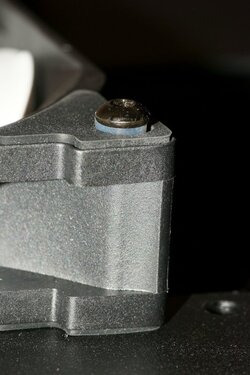
I haven't updated this build thread for a while - I sustained a severe knee injury back on New Years eve which is causing me some grief... Had an arthroscopy a couple of weeks ago so now just resting it as much as possible.

Not much fun....:(

Anyway - While all that was going on I did actually manage to perform some work on the build.

I also decided to order a pedestal for my SMA8 as I wanted the actual PC to sit on a short coffee table but be elevated enough so that the window/mobo section sits up at about eye level when sitting at a normal desk. Although in hindsight I could have just purchased a taller table....:D

As the pedestal has some room in there I decided to add another 560mm rad into the mix.

Here as some progress pics - Excuse the quality but I was limited in being able to move the case around due to my dodgy knee - so most photos were just shot against a bare wall with minimal lighting control.


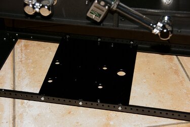
As the plumbing route has now altered due to the inclusion of the pedestal I had to fabricate a new pump mounting plate which was slightly longer. This allows me to add a pass-through connection to the plate which acts as a solid anchor point for the tubing.

Pump Plate v2.JPG


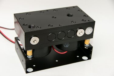
Last of the EK CSQ Dual D5 pump tops in captivity...? I much prefer this style over their latest offering.

I mounted the housing using some optional Aquacomputer soft silicone standoffs. These are much softer than the stock ones included with the housing by EK and should perform way better when it comes to vibration dampening. Unfortunately they only come in yellow and you cannot easily paint or colour these things - So yellow they stay...!

Dual CSQ Pump Block.JPG


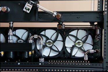
View of what was the bottom which now is the mid-section of my SMA8.....

I used 3 way rotary connections to and from the pump housing. Not so much for smooth coolant flow but more so to allow the pump housing to move freely on the vibration dampeners. With more solid type connections/fittings the pump housing would be restricted and vibes could more easily be transferred to the case via the tubing connections.

By using the multi 3-way joint rotaries it still allows the pump housing to freely move a fair amount due to the swivel movement in each joint which effectively decouples the complete assembly more effectively.

Mid Fan Shelf_Rear.JPG


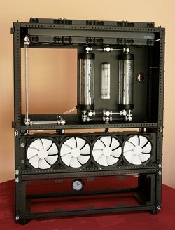
Current build so far.

Still need to add the third radiator after I modify the Caselabs rad mount slightly...

Case w_Pedestal.JPG


Lucky my height measurements for the complete dual reservoir assembly were fairly spot on - Not much room for error here: <5mm between the top of the res assembly and the fans - Just fits....:thup:

Res Clearance_b.JPG


BTW - The Phantek PH-F140MP fans seem really nice - I powered up the installed ones and they seem to have a really nice pleasant sound when running at various speeds - So far quite impressed.
 
Last edited:
Cover the yellow bits with black heatshrink?

Yeh - had thought about heatshrink but not sure if that is a good idea as it will stiffen up the damping action of the silicone.

I'm not too OCD about them being yellow since they will generally not be visible.
 
Last edited:
Drain plumbing.....

I'm a believer in having an easy to access, drip free drain system.

Sure, you can get by with a small random length of hose tucked up in their case - or some don't even bother with that as they simply disconnect an inline hose and dump the contents into a bucket.

However I wanted something that I can access very easily so that draining is not a chore and importantly I want a spill/drip free solution as I will be running a glycol based solution.

I'm a fan of fitting a mini valve to control my drain port - I currently utilise one in my 900D and would not consider a water cooling project without one. A few manufacturers make similar looking valves so most people can choose whatever favourite fittings they opt for - In my case Bitspower.

In my 900D I have a valve fitted at the very end of my bottom 480 rad - Easy to access via a removable cover and I was thinking along the same lines for my SMA8, except for one catch....!

My 900D drain setup:

Tubing_Rear.JPG


As my SMA8 is kitted out with 560mm rads, there is no available room at the very rear of the rad to incorporate a drain valve like I did on my 900D - So I had to come up with another idea.

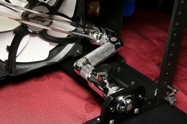
Another thing I wanted to resolve is that in many builds where they use the same Bitspower valve I have, the valve's tap/handle is actually quite tight to turn on/off and in many cases people mount them with one end unsupported. This can make them a tad unwieldy when you try and connect a long drain hose and operate the valve etc.

I wanted to ensure that the valve would be supported at both ends so that the valve would in effect be quite solidly mounted in place.

So this is what I ended up knocking up:

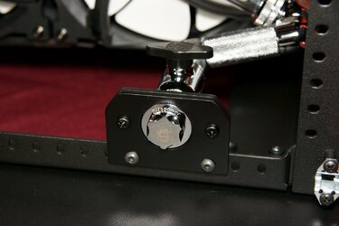
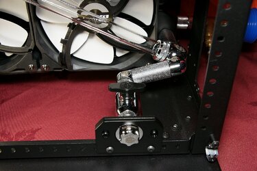
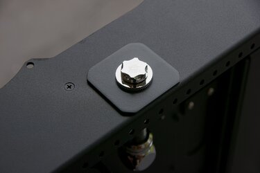
Fabricated a small bracket which is secured to the case - Bitspower pass through is recessed into bracket. Reason it is recessed was that I had to achieve the exact spacing for the fittings to mate correctly. Recessing it into the aluminium bracket allowed my those few mm (3mm actually) so that the fittings directly behind and inline with the valve all mated 100%.


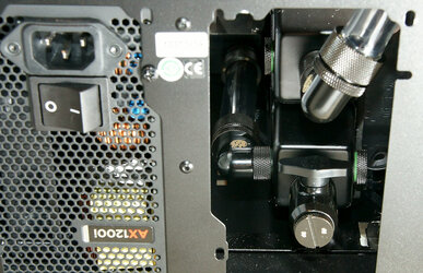
Drain port located at the rear right lower side in the pedestal - Easy access simply by popping off SMA8 pedestal side panel - Plenty of space to connect ancillary drain hose etc via the Bitspower pass through connection.

Drain Port_b.JPG


Connected to the most lowest point in the system which is pretty much the lower ports of the lowest rad in my case.

The pump feeds this very same port - so I had to use a 3 way block and a few other fittings to maintain the correct spacing etc to the valve.

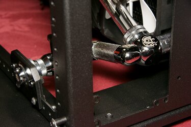
Ended up resulting in a very solid mount for the valve - It ain't going nowhere....!

A couple of pics from a few perspectives for those that are not all that familiar with these sort of drain setups:

The acrylic tubing run that you see is directly from my pump outlet...


Last edited:
Dang, you did it again, gave me ideas for my next build. Looks awesome, and cant wait for more updates. Look forward to hearing how this thing performs when you get it completed also. Again thank you for your help with the XT6, I must say it's the best controller out there.

Hope the Knee gets better, need more updates :D
 
Back