• Welcome to Overclockers Forums! Join us to reply in threads, receive reduced ads, and to customize your site experience!

[SOLVED] CPU/GPU blocks in parallel?

Overclockers is supported by our readers. When you click a link to make a purchase, we may earn a commission. Learn More.

iRemainStanding

Registered
Joined
Sep 11, 2015
I'm back again looking for more advice :D

Unfortunately I wasn't able to go through with watercooling a couple of months ago when I posted here in the first place. With tax returns just around the corner though, I'm going to start setting aside some money and finish it with a chunk of that. I've had quite a few ideas since I last drew up a layout guide and would love some pointers.

My components:
Case - Corsair 760T (white)
Motherboard - Gaming 7 Z97X (Gigabyte)
CPU - Intel 4790k
GPU - Diamond R9 295x2 (one for now, looking to pick up another one within the year)
RAM - EVGA SuperSC 2x8G 2400
PSU - Lepa G1600w

Parts I'm looking at:
Res - XSPC Photon 270
Pump - Swiftech MCP655 Series 12 VDC D5 Water Pumps - With Speed Control
Pump Top - EK-XTOP Revo D5 Pump Body - Plexi
CPU Block - Swiftech APOGEE XLC Clear
GPU Block - EK Radeon Radeon R9-295X2 VGA Liquid Cooling Block - Nickel
420 Rad - Black Ice Nemesis 420GTS Ultra Stealth U-Flow - Primer
280 Rad - Black Ice Nemesis 280GTS Ultra Stealth U-Flow - Primer
T Fitting - (2) - XSPC G1/4 black chrome
Res Top Adapter - (1) - XSPC M20 to G1/4 fillcap adapter - black chrome
Straight Fittings - (18) - Bitspower G1/4 matte black for acrylic tube OD 12MM (BP-MBEML)
Valve fitting - (2) - EK-AF Ball Valve (10mm) G1/4 - Black Nickel
Tubing - Bitspower non-champher Crystal Link 12MM OD
Coolant - To be decided, most likely an opaque white

Diagram:

Basically, the water would go pump/res -> 280 rad -> 420 rad -> cpu, gpu1, gpu2 in parallel -> pump/res

As the R9 295x2 blocks cover both chips in series, I'm assuming the flow rate would be much lower through these than the CPU block. I was thinking about putting a valve between the input of the CPU block and the T fitting that splits the loop. If I do this, I can fiddle with it slowly afterwards to try to limit the flow to the CPU block to about the same if not slightly less than the GPU's. Opinions?
 
Last edited:
If you want to run the GPU's in parallel, go for it. Don't run the CPU in parallel with the other blocks.
 
Yup, don't split the flow like that to the CPU block. Just have one line going to the CPU from GPUs and CPU to rad.
 
You can run it in parallel easy....

A cooling loop is a cooling loop. Series has its disadvantages. Lets say you have Reservoir, pump, GPU, CPU, close. All the liquid is doing is picking up heat at the GPU and carrying it to the CPU then back for cooling. So your CPU isn't really getting the attention it deserves. Obviously it isn't that big of a deal since everyone does it this way but lets entertain the idea of parallel. this is how it should be set up:

................Pump- GPU - flow meter
Reservoir<...................................> Reservoir
................Pump - CPU - flow meter

(don't mind the periods, It was the only way I could make my chart work)

The flow meters are recommended because you can make sure everything is getting the juice it needs but by putting the pumps AFTER the split for the reservoir then the flow will be powerful. Although with this you will need a large enough reservoir to dissipate the heat because that water will be moving fast.

I will be doing this with my build in a few months, Look for my thread!


I'm back again looking for more advice :D

Unfortunately I wasn't able to go through with watercooling a couple of months ago when I posted here in the first place. With tax returns just around the corner though, I'm going to start setting aside some money and finish it with a chunk of that. I've had quite a few ideas since I last drew up a layout guide and would love some pointers.

My components:
Case - Corsair 760T (white)
Motherboard - Gaming 7 Z97X (Gigabyte)
CPU - Intel 4790k
GPU - Diamond R9 295x2 (one for now, looking to pick up another one within the year)
RAM - EVGA SuperSC 2x8G 2400
PSU - Lepa G1600w

Parts I'm looking at:
Res - XSPC Photon 270
Pump - Swiftech MCP655 Series 12 VDC D5 Water Pumps - With Speed Control
Pump Top - EK-XTOP Revo D5 Pump Body - Plexi
CPU Block - Swiftech APOGEE XLC Clear
GPU Block - EK Radeon Radeon R9-295X2 VGA Liquid Cooling Block - Nickel
420 Rad - Black Ice Nemesis 420GTS Ultra Stealth U-Flow - Primer
280 Rad - Black Ice Nemesis 280GTS Ultra Stealth U-Flow - Primer
T Fitting - (2) - XSPC G1/4 black chrome
Res Top Adapter - (1) - XSPC M20 to G1/4 fillcap adapter - black chrome
Straight Fittings - (18) - Bitspower G1/4 matte black for acrylic tube OD 12MM (BP-MBEML)
Valve fitting - (2) - EK-AF Ball Valve (10mm) G1/4 - Black Nickel
Tubing - Bitspower non-champher Crystal Link 12MM OD
Coolant - To be decided, most likely an opaque white

Diagram:

Basically, the water would go pump/res -> 280 rad -> 420 rad -> cpu, gpu1, gpu2 in parallel -> pump/res

As the R9 295x2 blocks cover both chips in series, I'm assuming the flow rate would be much lower through these than the CPU block. I was thinking about putting a valve between the input of the CPU block and the T fitting that splits the loop. If I do this, I can fiddle with it slowly afterwards to try to limit the flow to the CPU block to about the same if not slightly less than the GPU's. Opinions?
 
Last edited:
Um...no. I don't know where you got your info from, but flow meters are NOT recommended. It hurts flow, puts strain on the pump and is not needed. It's a novelty and a waste of money. If YOU want to add flow meters to YOUR build that's YOUR prerogative. Please refrain from submitting help with misinformation.

With 2 radiators, the OP will benefit from running his loop in series as witchy recommended.
 
A cooling loop is a cooling loop. Series has its disadvantages. Lets say you have Reservoir, pump, GPU, CPU, close. All the liquid is doing is picking up heat at the GPU and carrying it to the CPU then back for cooling. So your CPU isn't really getting the attention it deserves. Obviously it isn't that big of a deal since everyone does it this way but lets entertain the idea of parallel. this is how it should be set up:

Have you built a WC loop? Understand the physics and the 1000's of people that have tried a parellel loop?

First thing. The flow meters used in PC watercooling are crap unless you spend $80 each and have a $200 board to interface with them. Or more. They restrict flow, they quit turning the little flapper wheel, they are another connection that can leak. Nuff said on that.

NM, the OP has ben AWOL for the last 12 days, so no need to continue this to explain to the OP why parallel is WRONG.
 
Sorry guys, forgot I posted this.

Thanks for all the feedback everyone. I knew posting this that it wouldn't be the very best when it comes to performance, but I was hoping that putting a partially closed valve before only the CPU would sort it out for the most part. Guess I'll just do them in series.
 
If/when I pick up a second R9 295x2, I'll probably use a parallel bridge. They'd have the same block though, so uneven flow isn't a problem there.
 
If/when I pick up a second R9 295x2, I'll probably use a parallel bridge. They'd have the same block though, so uneven flow isn't a problem there.

Parallel is ok for SLI GPUs. Literally the only thing that could be run parallel in a loop. Everything else shouldn't. :thup:
 
If you read my post I'm pretty sure I said that the flow meter is just to make sure it's flowing.... for this I recommend it. If you have 2 pumps pushing 1 circuit does the resistance really matter? Every water pump/ water meter used in construction and engineering has a flow meter, why wouldn't you want one when you are engineering your cooling system? I think you're just tying to find something wrong. I would also assume that you are an omniscient being that was blessed by the IT gods, or at least that is how you're acting.


Um...no. I don't know where you got your info from, but flow meters are NOT recommended. It hurts flow, puts strain on the pump and is not needed. It's a novelty and a waste of money. If YOU want to add flow meters to YOUR build that's YOUR prerogative. Please refrain from submitting help with misinformation.

With 2 radiators, the OP will benefit from running his loop in series as witchy recommended.
 
If you read my post I'm pretty sure I said that the flow meter is just to make sure it's flowing.... for this I recommend it. If you have 2 pumps pushing 1 circuit does the resistance really matter? Every water pump/ water meter used in construction and engineering has a flow meter, why wouldn't you want one when you are engineering your cooling system? I think you're just tying to find something wrong. I would also assume that you are an omniscient being that was blessed by the IT gods, or at least that is how you're acting.

We live in a world (PC watercooling) where flow meters are unnecessary because we can test how good our flows are via temperature readouts.
This removes restriction from the loop and goes easier on the budget.
 
I'm going to respectfully disagree with some of our veteran members here as I believe flow meters aren't a necessity but could be helpful and aren't that big of a deal if the funds are there for one. If it wasn't for my meter, I wouldn't have noticed my loops deterioration prior to temps showing any signs. I mentally prepared myself for the tear down months down the road till I felt after the 20c difference that it was time for investigation. I still use my flow meter as it tells me what speed I can set up my pump with tolerant audibles while maintaining the sweet spot. I never regretted the purchase of one.
 
Just need to purchase the 'right' flowmeter.

Many of the cheaper units that have some form of visible rotary impeller are prone to problems.
 
Last edited:
Okay so I will agree that the flow meter does create drag but have you done it from a mathematical perspective? Lets take an average Pump Swifttech MCP350. It pushes 116 gallons per hour. Now a flowmeter causes a 5% drag. so instead of your pumping pushing 116 gallons in 1 hour it now pushes 111.8 gallons per hour. So, if you are running parallel with joined reservoirs then you are pushing 232 gallons per hour WITHOUT the flow meters or 223.6 gallons per hour WITH them. Hmmmmm.... Is this going to cause any issue with the pump or temperature of the system. I think not.

Flow meters serve 1 purpose, to watch the water flow. All this stuff about it putting stress on the pump is just people worrying over nothing.

Again, I understand where y'all are coming from but for an engineers perspective, there is no difference. It's basic math. If your pump will last say 3-4 years approx without the drag, then we could say that the pump will last 2.9-3.9 years with the drag.
 
I'm pretty sure that if you split the loop, it also splits the pressure and flow. I believe that means this would be pumping 58 gallons per hour.
 
That's a negative ghost rider, over. Using my chart above as a reference, You will see that there are 2 pumps. Both come immediately after the split from the reservoir ensuring full force from each "leg" of the circuit.
 
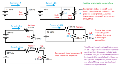
Pressure and flow follow the same laws as voltage and current.

If you add a parallel loop, you decrease system pressure drop (resistance in electricity). Hence the pump (battery) will provide more flow (current). Like a real battery, flow increase doesn't have to be linear. You need to check the pumps output specification at different pressures. But theoretically, by the laws for physics, adding a parallel loop could double flow.

Flow meters are just another source of pressure drop, should have no impact of pump besides reducing flow.

See below. Lots of assumption made, so can't be used in real life but can be used to demonstrate points. The flow meters mentioned about could be used to measure internal resistance to develop real numbers for below and provide useful information.

Source: I am mechanical engineer. Flow.png

Edit to picture above, in purple text, where is says temperature in water would be lower should be could be lower. Depends on rad and fans attached. Could be higher too if rad is undersized, etc. Anyways like I said above, lots of assumption.
 
Last edited:
Kasm,

With that said you do realize that electricity travels from negative to positive and only AC current travels both ways. Water flows in the path of least resistance. Also when you you involve Electrical the formula changes completely. Electrical formula is Watt, Voltage and Current. The Amps in the circuit is the current so that is what we would be looking at. If you put 2 batteries in parallel then the current (amps) double therefore proving my point. So you just helped my case while you were thinking you actually had an argument.

Plus a BIG difference in the flow of electricity and water is simple, with the water you have to take in account for the viscosity, water gravity and a few other things, I can post the equation if you would like.

While most of your chart looks good other than your blue current lines, which are traveling backwards because DC voltage travels negative to positive. The short line for the battery symbol is the negative, long line positive. If this was an AC circuit then your arrows would be correct but your battery symbol would be different.

And as for your comment about the flow meters, you're beating a dead horse. No comment.

It's cool that you're a fellow engineer but you have to dot the "i"s and cross those "t"s my friend. You're suppose to be an engineer.

Remember AMPS is the CURRENT which is what we are talking about and water is not the same as electricity.
 
Back