• Welcome to Overclockers Forums! Join us to reply in threads, receive reduced ads, and to customize your site experience!

PWM Control of LED Strips

Overclockers is supported by our readers. When you click a link to make a purchase, we may earn a commission. Learn More.

hydroracer_99m

Registered
Joined
Nov 3, 2015
Hello all,

Everybody knows it's cool to have LEDs in your case, whether in strips or otherwise. It's even cooler to be able to control these, namely brightness if you only have one color. There are 5.25" bay control solutions, but as an owner of a case without such a bay, I'm looking for a different solution for brightness control. I have some experience using an Arduino to PWM a small LED around 1000Hz, but I'm looking for a bigger better solution for more LEDs and from a different PWM source. As an aerospace engineer, I don't know as much about semiconductors and their implementations as some of you guys out here, so I was hoping for some guidance on what I think is a pretty cool idea.

PWM motherboard fan headers provide usually a 25kHz PWM signal at 5v and 5mA from 0-100% duty cycle, something ideal for PWM fans to read and be controlled by. However, I think this PWM source would be ideal for LED control. The challenge is "amplifying" that PWM source to a 12V signal between 1-2A for a good number of LEDs. My experience tells me there should be a relatively simple implementation of a MOSFET or bipolar junction transistor to use the 5v signal to switch a 12v signal to power the lights, but I don't know what other details need to be considered here. I know this type of modulation exists in LED drivers and stepper motor drivers, but I'm looking to implement it in this case.

I hope somebody who has more semiconductor experience can lend some guidance, I think this would be a super cool thing to have implemented because then you could for instance set up a profile in speedfan or control it manually or all these things, and even control an RGB strip if you have three PWM channels available.

Thanks guys!
 
I have tried putting LED bars on fan controllers and motherboard fan headers and they tend to just blink when you go too low.
I found that a voltage switch is much simpler and faster then dealing with PWM control.

Couldn't you look at one of the 5.25" bay controllers you speak of and duplicate it? Or maybe a rheostat/potentiometer?
Sorry I can't be much of any help here other then that. I don't do much with led's.
 
There are RGB LED strips on the market, with an IR remote, that can control the following:
- Brightness
- Color
- Type of Pattern
- Speed of Pattern

If you still want to do the work with a custom board, consider taking the PWM input to the board and using it as a PWM -> Voltage controller.
Another option would be to take a PWM signal and use it as a reference signal to drive the output of the board (using a secondary power connector) at a higher power.
 
The thing is that LEDs don't really respond to voltage changes due to their nature as a diode. They prefer to be run as a constant-voltage variable-current device, and many people have fried LEDs from trying to control the voltage. Without proper current limiting (variable resistor, other driving circuit, etc) if you drop the voltage, the LED will just draw more current. The same goes for pushing too much voltage, with a constant current the power will increase beyond the diode's spec. There are electronics equations that are beyond me that govern the interaction of voltage, current, and temperature in a semiconductor, and those dictate a case of thermal run-away if current is not regulated during voltage change, or even regulated current in any mode of operation. While we are used to varying the voltage to create brightness changes in incandescent bulbs, they are current limiting devices themselves and are governed by the changing resistance of the filament dependent on the temperature.

So really, the long and short of it is that LEDs should NEVER be driven or controlled by voltage alone. LEDs can be dimmed by say a variable resistor in series with them, regulating the current and inducing a power and thus voltage drop across the LED and keeping the diode from running away from itself and being destroyed. Motherboard fan headers can vary voltage to a fan because the fan responds to the lower voltage and draws less current and keeps itself in check. The purpose of PWM is to keep the state of the LED the same, meaning the voltage will always be the same and a static series resistor can be used to regulate the current. This will keep the LED stable while being turned on an off very rapidly. We perceive this as a brightness change, since the true average power output over time is indeed lower. It's like a buck converter for modifying voltage; even though the power source is really the same intensity, when switched on and off rapidly the actual output power will be lower. Inductors and capacitors do that work in a buck converter, and our eyes to that work when an LED is cycled quickly enough.

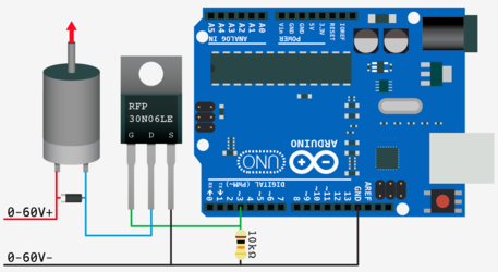
So coming down to it in the scope of my endeavor, I will keep the voltage and current constant to my LED array (12v over the strip that I have) and cycle the voltage from 0 to 12 rapidly, effectively changing the brightness. Following some research on controlling higher-power electronics from low power sources like an Arduino, all it takes is a properly-specced MOSFET with the 5v, 5mA PWM signal from the motherboard along with a 10k pull-down resistor to switch really any voltage and current that the specs of the MOSFET allow. This is a common way to control motors or other high-power components from a source like an Arduino that can't really provide much oomph. The MOSFET in the middle does all the work.

In fact, PWM is a common way that the 5.25" bay devices control brightness. All it takes is a 555 timer chip and a variable resistor to produce a high frequency variable duty cycle signal to the lights. I'm sure there are designs out there that do regulate current and voltage simultaneously but that would undoubtedly be more complicated. I am very well aware of the products on the market and how they are integrated, but I found nothing to my liking and wanted to come up with a unique solution that suits my needs perfectly.

I'll get back to this post with what I find, as I think if my method works and is easy it could be something other users could take advantage of, especially with the potential for tight integration with a software like speedfan or really any method of controlling the PWM duty cycle on the motherboard header. It should be an exciting project and I'm looking forward to getting it to work.
 
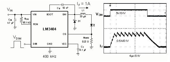
Here you go...1 A driver...found it with a quick Google search:

LED PWM.jpg

I've done something very similar in the past for high power LED applications. You connect the PWM signal input "VDim". You'll have to lookup the chip to make sure that you have the chip voltages right for Vin and VDim. There are others in the series.
 
What's the advantage of a dedicated driver like this over just using the PWM signal to switch a higher power source?
 
All LEDs are dimmable via PWM, that's part of the whole point. Those are just sleeved nicely with a system of connectors. The issue at hand is that the PWM source, the motherboard, doesn't have enough power (only 5mA at 5v) to drive any decently sized LEDs, so that PWM source has to be amplified. The implementation of that type of amplifier was the goal of this post, the result of which seems to be a simple MOSFET to switch a higher voltage signal with greater current capability.
 
The LEDs don't really dim when you PWM them, they just turn on and off a lot. As you leave them off longer in the PWM cycle, they appear dim as they are producing less photons on average.

The trick is to turn them on and off fast enough so that your eye can't tell the difference. Your eye in an "integrator" and will "average" the on and off pulses. This is similar to how your TV works, a movie at the theater works, or even how a regular light bulb works.

In not notice the flicker, you need at least 30 Hz for the PWM frequency. It's best to not have the frequency be a multiple of power line frequency (60 or 50 Hz depending on where you live) to avoid the "flickering" that you used to see with old CRT screens.


Yes I understand the concepts of PWM for brightness control, as I explained in my previous posts. As I also said above, the motherboard fan header PWM frequency is specified to be 25KHz, far above what our eyes can perceive and above the audible range for most people too. This is also the frequency that many other PWM-controlled devices run at, again to avoid the audible range of frequencies. There is no issue here with the concept of PWM-ing an LED to effectively ("effectively", meaning to our eyes) the issue that I believe I have resolved is using the motherboard PWM signal as a source for this control.
 
It's a great idea...didn't mean to offend!

You were going down the right path. Motor drivers work nice too. Check out Linear Technology and Analog Devices...they have some nice chipsets which do this...and breadboard kits.

The biggest challenge you will have is keeping the output trace from the main power FET thick enough and short enough. If it's to thin, the extra inductance will kick the voltage up when you turn off the LEDs...if you are not careful you can overvolt and pop them.

The chipsets have the FET built in with feedback circuitry to help compensate. If you use a FET by itself, make sure you setup a feedback loop.

Sounds like a fun project! :D


No offense taken! Sorry if I was short.

Right, I have heard of that kind of kickback in a circuit of this type but primarily in electromagnetic devices like solenoids or motors that are being switched. Are you talking about the PCB trace from the FET being thick and short? From what I've been devising, I'm thinking of having the circuitry be pretty compact and simple, I wasn't planning a PCB. I've mostly been referencing people controlling higher power components from Arduinos, such as laid out in the attached image. I don't really know why it would be more complex than this, provided a proper FET is chosen to meet the needs of the circuit. There is a kickback-preventing diode in this circuit, but you made it sound like it may need to be a bit more complicated than that. I just figured it may not be as simple as this diagram indicated, so that's why I'm coming to you all!

rfp30n06le-arduino-solenoid.png
 
Could always go with one of those ASUS ROG boards with the built-in 12V RGB header!

I'm actually considering going with that option to combine with the Phanteks Enthoo Luxe case. Woo shiny lights?
 
Back