• Welcome to Overclockers Forums! Join us to reply in threads, receive reduced ads, and to customize your site experience!

Raspberry Pi Zero Gameboy

Overclockers is supported by our readers. When you click a link to make a purchase, we may earn a commission. Learn More.

BlueNostromo

Member
Joined
Mar 24, 2015
So i purchased a few Raspberry Pi Zeroes a few days ago and I have RetroPie running on one of them. I have purchased this display (3.5" touch screen that uses the 40 pins) http://www.ebay.com/itm/221868026906?_trksid=p2057872.m2749.l2649&ssPageName=STRK:MEBIDX:IT

The only way I have seen people connect controllers is using the same 40 pins. I doubt I can wire up the controller and the screen to those pins at the same time, so I guess I would be forced to use USB?
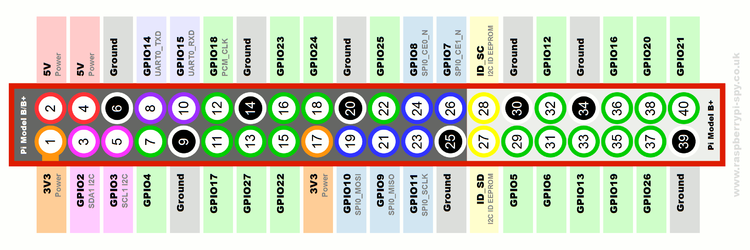
 
You have to note which pins the display actually uses. Then make sure the buttons are connected to GPIOs not used by the display.
 
Raspberry-Pi-GPIO-Layout-Model-B-Plus-rotated-2700x900.png

The display uses pins 1-26. Leaving me the other 14. From what I gather I cannot use the ID_SD pins for my use. That leaves me with 9 IO pins (the green ones right?). I can connect any or all of these green pins to the 3 common ground pins to use them as buttons?
 
Connect the buttons between the GPIOs and ground. Also add 10k pullups from each GPIO used for buttons to the 3.3v supply

You'll probably want to save the USB for other purposes like plugging in a USB drive to save games onto.
 
Also add 10k pullups from each GPIO used for buttons to the 3.3v supply

I have a 32gb sd card so space should be a non-issue. You are saying add a resistor connecting the GPIO being used and 3.3v? What is the reason for this?
 
Last edited:
So the system will think "if not receieving 3.3V on GPIO 'x', then 'x' button is pressed"?
 
Back