• Welcome to Overclockers Forums! Join us to reply in threads, receive reduced ads, and to customize your site experience!

[SOLVED] Built a PWM controller but one fan refuses to obey it

Overclockers is supported by our readers. When you click a link to make a purchase, we may earn a commission. Learn More.

SoleSoul

New Member
Joined
Mar 8, 2012
Hi. I'm new here.

I built a PWM controller according to http://www.overclockers.com/forums/...r-4-wires-PWM-fan/page2?p=6473318#post6473318
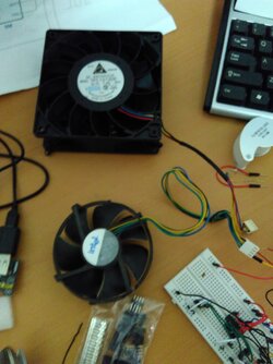
It works well on a led and on an Intel supplied Nidec CPU fan. The reason for doing it all though was to have a controllable strong fan so I bought a Delta TFC1212DE off ebay. Sadly, the Delta fan always runs at full speed and doesn't respond to the PWM signal from the circuit. I tried an inverted signal also, nothing.

I tried many things but I'm out of ideas at this stage.
What can be the reason for the fan not to respond to the PWM signal at all?

Thanks!
 
Last edited:
I'm just taking a shot in the dark here but if it working with your other fans it sounds like you got a bad delta fan from eBay or a knockoff. If you have a pwm splitter that allows you to grab the signal from the mobo and power from the psu, you could test the fan that way and eliminate the pwm controller temporarily. This would tell you if it is a fan or a controlled issue.
 
Is the Delta in question intended for HVAC or other non PC applications? I have one intended for a Daikin indoor unit and it would not respond correctly to a standard PWM signal. Since I don't have that indoor unit to reverse engineer, I just played around and found that it seems to work well with 1kHz inverted PWM.
 
Thank you for helping.

if it working with your other fans it sounds like you got a bad delta fan from eBay or a knockoff
This is the fan that I bought: http://www.ebay.com/itm/NEW-Delta-1...206651?hash=item3f4e6561bb:g:UrkAAOSwrklVeQrr

If you have a pwm splitter that allows you to grab the signal from the mobo and power from the psu, you could test the fan that way and eliminate the pwm controller temporarily.
I still prefer not to connect it to an actual computer but I may try it later if I won't be able to figure it out otherwise.

Is the Delta in question intended for HVAC or other non PC applications?
How can I know? (Please see the link above and pictures below)
Should I try to feed it a 1kHz signal anyway? How would I change the frequency to 1kHz? By changing the 470pF capacitor to something else? Can you help me with this?

Did you buy a TFC1212DE or TFC1212DE-PWM?
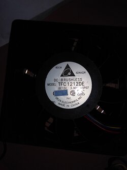
I think it's a PWM fan but it's not written explicitly on the label. Can you tell from the link above and the pictures below?

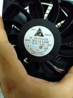
The label
IMG_20160517_092024.jpg


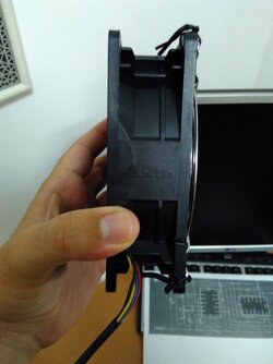
Side
IMG_20160517_092037.jpg

IMG_20160517_092045.jpg


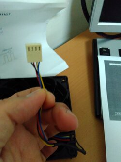
Connector
IMG_20160517_092106.jpg


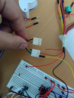
Connector comparison. The top is the Delta, bottom is the Intel.
IMG_20160517_092129.jpg


Both fans
IMG_20160517_092138.jpg


By the way, the whole project is an air blower for a blacksmithing forge. I messed around with other cheap blowers which broke quickly and since I am a computer guy I thought, why not take a strong server fan and try to build a good blower from it? It sure will run for some time before it breaks since these fans are designed to work for long periods of time.

:)
 
Last edited:
It should be PWM, per their description.
Looks like the two fans have different pinouts, confirm your wiring to the fan matches what is on the listing.
 
It should be PWM, per their description.
Looks like the two fans have different pinouts, confirm your wiring to the fan matches what is on the listing.

Do you think that it's possible that pin 3 is the PWM control?
Would it hurt to try and connect the PWM signal to the 3rd pin if it's the tach?

(did I understand your post correctly, that you are referring to the position of the PWM pin on the connector?)
 
Last edited:
Do you think that it's possible that pin 3 is the PWM control?
Would it hurt to try and connect the PWM signal to the 3rd pin if it's the tach?

(did I understand your post correctly, that you are referring to the position of the PWM pin on the connector?)

Look at the pinout on the eBay link you gave. They detail what each pin does.
 
Sorry but I really can't find the pinout on the page.
The whole description is this:
Delta 120mm 12cm PWM TFC1212DE 252CFM 12038 DC 12V CPU Cooling Fan

Detailed Product Description:
For Delta TFC1212DE-PWM, 120x38mm-4pin PWM+Tac Sensor, 252.8 cfm Most Powerful in 120x38mm form factor!
This fan is the equivalent spec with PFB1212UHE-F00, only with PWM control.
PWM fan connector you can let your motherboard keep this fan running at minimal speeds and still have the high end for those times when you really need it.
Features :
Extreme high airflow and static pressure
4 wire with PWM Control
Speed sensor (Tach Out Put)
The most powerful in 120x38mm form factor!
Note: Please make sure your board can handle the power consume by this fan.
Dimension 120 mm x120 mm x 38 mm
Connector 4 Pin
Cord length 90mm

What are you referring to?
 
Wow, apparently I was seeing things? Looks like I need to remember coffee before forums...

Anyway, I would just swap the tach output and PWM control pins and see what happens.
It looks like the fan you have is backward from the AFC1212D-PWM fans I have, which work on a typical PWM control circuit.

They are:
- Black
- Red
- Blue
- Yellow

Where yours is:
- Black
- Red
- Yellow
- Blue
 
Again, the simplest solution is the correct one.

Why would they put the PWM pin as the 3rd and yellow colored is beyond me but thanks to you I tried it and now everything works.
All that is left now is to limit the circuit to minimum ~20% so the fan won't turn off.

I love you all!
:)
 
Woohoo!!! Glad I happened to think about the old AFC I have to check the pinout of.
 
And "lack of coffee thinking I saw things I didn't" skills! Haha

Can't wait to see the project done :)
 
Beware that if you plan on running it full power for long, that connector isn't really rated for the current and may soften to the point of no longer making a good connection. They can get away with it if there's plenty of airflow over it.
 
Is the connector the weakest link?
It's good that you tell me this because I can arrange that the connector will be positioned somewhere in the air flow.

Would changing the connector to another after market (ebay...) one help?

If all fails, I can always get rid of the connectors and solder the cables directly I guess.
 
Back