• Welcome to Overclockers Forums! Join us to reply in threads, receive reduced ads, and to customize your site experience!

FEATURED Buidling a Benching Station Navig Style

Overclockers is supported by our readers. When you click a link to make a purchase, we may earn a commission. Learn More.
Thank You!


My tool preference to make all these cutout slots:


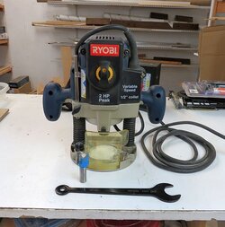
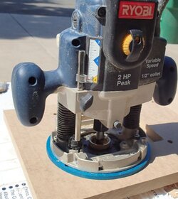
The Router


Router%2Bpic.jpg


What are the advantages of using the Router method over the Make-2-holes-and-connect-with-jigsaw method?

I find drill-holes-jigsaw method, it's often difficult to meet the straight cuts to the holes perfectly--so you end up with a bunch of sanding and it still often doesn’t look right. With the router done carefully, it looks like the slots are machined in, which they are because this is how a CNC mill works.


Router Basics

A router is basically a tool that spins bits really fast. Most people have a Dremel rotary tool--a router is a Dremel on steroids.

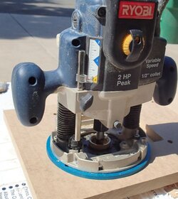
I use the pretty inexpensive router pictured above, but it has some important features:

Fits ½” collar size bits (some routers fit ⅜”. A Dremel fits ⅛”) ½” shank bits are bit more stable so I like that.
Variable speed--if you spin too fast and sit still, you can catch MDF on fire.
Plunge routing--the frame allows me to start my bit spinning, then plunge the bit into the material surface, with an easy lever to lock it in at a particular level.
Accurate depth stops (see my future section on Advanced Routing/CPU hole cutout).


Router Setup

Here’s how I set everything up to create one of the cutouts:


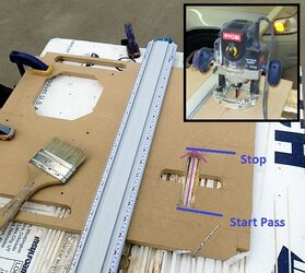
Router%2Bstraight%2Bedge%2Bguide2.jpg

First I like to place my panel on a sacrificial surface (some rigid foam insulation). That way I can route all the way thru the panel without worrying about destroying something underneath.

Then I set up a straight edge so that my bit will align with my planned cutout slot.

It's important to make big pencil marks to clearly show stop points--things will get dusty and you don’t want to miss your mark.

Then it's time to make a pass with the router.

First, make sure the router is set up. Since I’m going to make slots with ⅞” thickness with ⅞” rounded ends, lock in a ⅞” router bit, duh. Select your appropriate speed. If you want, select a depth of ⅛” below the router plate--since the ultimate plan is route all the way thru the panel, you can just freehand the depth.

I highly recommend making a mock pass just to make sure your straight edge is locked in, the router moves smoothly, nothing is getting caught (ie power cables).

Then with the bit lined up at the start line, but not engaged with the material, I will fire up the router.

Once the bit is up to speed, I plunge the bit into the material, to the approximate depth of ⅛”.

After achieving that depth, I will lock the depth in, and make my first pass.

Slowly work the router to the end of the pass, then disengage the depth stop, lifting the bit off the surface, and shut it down.

At this point, I vacuum all my dust away and make sure it was nice clean pass.

It is critical to keep everything clean and dust free--particularly make sure nothing builds up next to your straight edge clamp or this will throw off the next pass.

I will typically do 3 or 4 passes, each increasing the depth by about ⅛”, until I hit my sacrificial surface, and voila, you’ve got a rounded ended slot cutout perfect for cables and pipes!


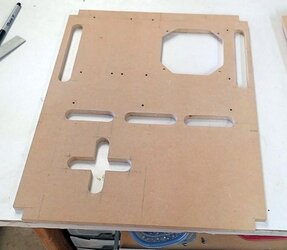
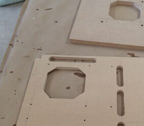
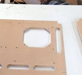
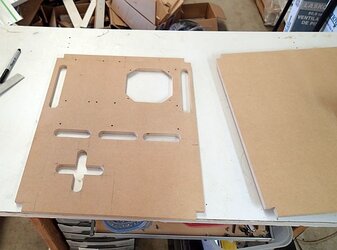
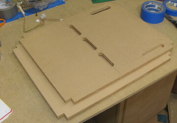
Here’s the panel with all the nice cutouts all done with the router:

Station30%2Btop%2Bpanel%2Bmilled.jpg
 
Last edited:
Main Structure: Panels


Step #5
Make your panel cutouts

The Under the CPU socket cutout


It’s nice to access the underside of the motherboard. The first few times I started cutting out a panel under the cpu socket, I just cut a rectangular hole.

Then clients started requesting the ability to mount a 120mm fan underneath the cpu socket.

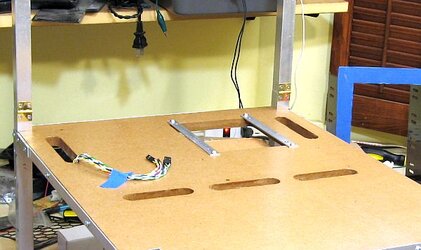
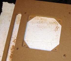
So then for a while I was cutting out holes underneath the cpu socket and then adding back 2 pieces of aluminum trim with holes to mount a 120mm fan, as you can see I did for Station #16:


CPU%2Bcutout1.jpg


A 120mm fan cpu socket cutout was requested so often I decided I wanted to “automate” the task.


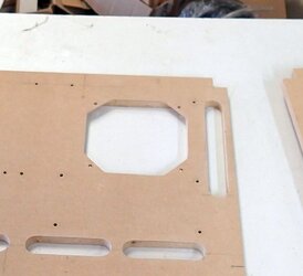
If you look back up at the picture above of the completed routed slots on the previous post, you will also see my new-and-improved automated 120mm cpu socket cutout:


CPU%2Bsocket%2Bcutout%2Bfinished.jpg


No extra trim pieces! All done with the router.
 
Last edited:
CPU Under Socket Cutout with 120mm fan mount--Advanced Routering!

Principle #1: The Jig


A Jig is a pre-cut guide for the router.

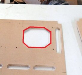
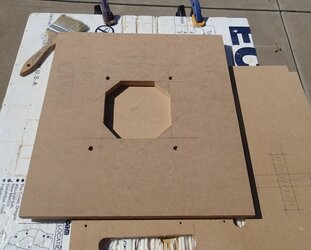
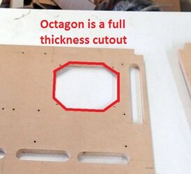
For example, in this picture, I used a jig to cut this octagonal shape.


CPU%2Bsocket%2Bcutout%2Bfinished%2Blabeld%2Bsmall.jpg


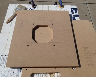
Here, in fact is my jig.
Router%2Boctagonal%2Bjig.jpg

As you can see, it is octagonal shaped, and it mounts to 4 of the motherboard mount holes, so it is always located in the same place. The octagon of the jig is exactly ⅛” larger on all sides than my end result hole (explained later), and was cut out with my scrollsaw out of ½” thick MDF.


In order to get a router to follow a jig, you need to obtain a Router guide bushing kit and a router plate.

http://www.rockler.com/router-guide-bushing-kit

http://www.rockler.com/guide-bushing-router-plate


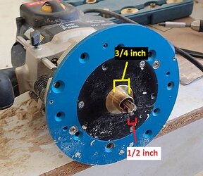
Here is the setup mounted to my router with a ½” straight bit and the ¾” OD (outer diameter) template guide.

Router%2Bplate%2Blabeled.jpg

In this setup, the jig would be mounted on top of the panel you wish to route. The brass portion of the template guide then interacts with the inside edge of your jig, while the bit will plunge into, and then carve out the same shape of the jig in the target panel below.

Since there is a gap of ⅛” between the outside edge of your router bit and the outside edge of the brass guide, your final hole in the target panel will be smaller than the jig by ⅛” on all sides, which is why I mentioned earlier that the jig needed to be ⅛” larger on all sides than your desired end hole.


Here is what that process looks like in a stepwise fashion:

1) Mount the jig, using the 4 holes aligned with motherboard mounts.

Router%2Boctagonal%2Bjig.jpg


2) Hit it with the router + template guide setup.
Place the router with the edge guide abutting the jig. Start the router. Plunge to the appropriate depth and lock in the depth. Slowly move the live router along the inside perimeter of the jig. When done, release the depth lock, turn off the router, and vacuum away the dust.

Router%2Bon%2Bjig.jpg


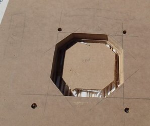
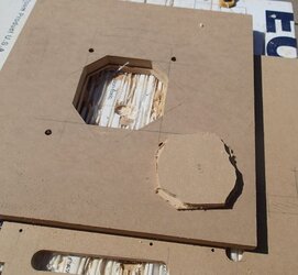
3) Here it is after routing.

Router%2Boctagonal%2Bcut.jpg


4) And here is the final octagonal hole
Octagonal%2Bcutout.jpg
 
Last edited:
Well then, let me show you my next trick!


CPU Under Socket Cutout with 120mm fan mount--Advanced Routering

Principle #2: Depth Control


The second part of my Advanced Routering is the use of depth control.

For my CPU socket hole, one side is the octagon shape, which leaves corner tabs for the screws to mount the fan.
This shape is cut entirely thru the whole depth of the panel.

CPU%2Bsocket%2Bcutout%2Bfinished%2Blabeld%2Bsmall2.jpg


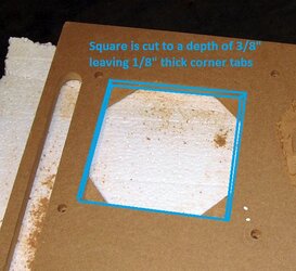
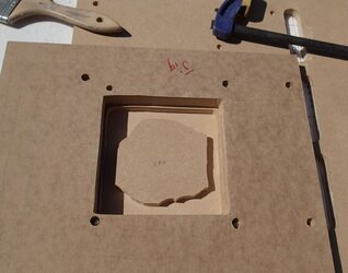
However, when viewed from the underside, there is a second cutout shape--a simple square sized to fit a fan, but the square is not the full thickness of the panel, so it leaves material for the corner tabs.
The depth of the square is ⅜”, leaving the tabs to be a thickness of ⅛”, since the panel is ½” in thickness.


Fan%2Bhole%2Bcutout1%2Bsquare.jpg


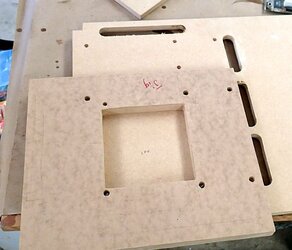
So, approaching from the bottom side I first secure my square jig (remember the size of the square is the size of the desired rectangle (120mm) + ⅛” on all sides + tiny safety margin).


Rectangular%2Bjig.jpg


Then I set the depth stop on my router to 3/8".
Drop the router in place.
Start the router.
Plunge until I hit the depth stop.
Trace out the rectangular jig.


Router%2Bon%2Bjig.jpg

Rectangle%2Brouted.jpg


Notice I don’t actually have to route away the entire rectangle, because I know the next step I’m going to route away the perimeter octagon to full thickness.


Next I attached my octagon jig. And this time set my depth to punch thru the entire panel.


CPU%2Bsocket%2Boctagon%2Bcut.jpg


Here is the hole cut out, plus drilling the fan mount holes.


CPU%2Bsocket%2Bcutout%2Bfinished.jpg


Completed, this is what it looks like from the underside:


CPU%2Bsocket%2Bunderside.jpg


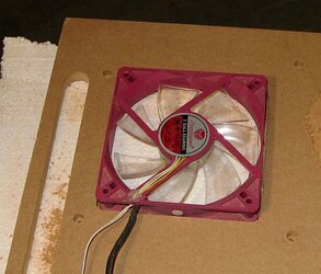
And with a fan mounted--the fan actually sits recessed, which is nice--leaves more clearance for the components underneath.


CPU%2Bsocket%2Bwith%2Bfan1.jpg


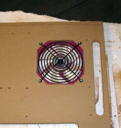
And from the top with a fan mounted:


CPU%2Bsocket%2Bwith%2Bfan2.jpg


And that is how I do a Jig guided recessed Under CPU Socket Fan mount with just a router.
 
Last edited:
Main Structure: Panels Complete!


In summary:

1. Rectangular panels of ½” thick MDF were cut to size.
2. Corner were notched.
3. Motherboard mounting holes were drilled.
4. Pass throughs were routed.
5. CPU under socket fan mount was milled.


Panels%2Bcomplete.jpg


All that is left is to finish the panels, which I will cover later in the Aesthetics/Trim section.


On to constructing the posts....
 
Last edited:
Main Structure: Posts


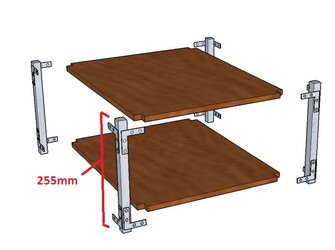
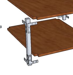
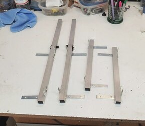
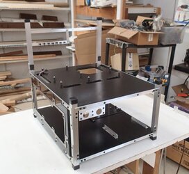
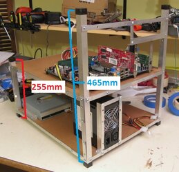
The basic structure of the posts consists of ¾” square tube aluminum posts, each 255mm in length. Each post will then have 4 L brackets riveted to them to attach them to the wood panels.


Bars%2Bn%2BPlates%2B255.jpg


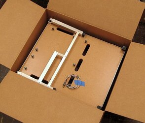
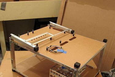
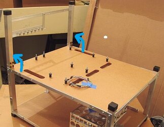
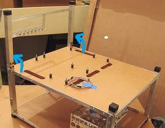
On one end of the station, the PCI brackets extend above the posts, and are also based on ¾” square tube aluminum. In my design, I have the PCI bracketry as a separate unit from the base posts, and then I attach them to the posts with hinges and a locking mechanism. This is mostly for convenience of storage and shipping. By hinging the PCI brackets, I can fit the station into a much smaller box.


PCI%2Bbracket%2Bflip%2Bup1.jpg

PCI bracket folded down, fits in a box better


PCI%2Bbracket%2Bflip%2Bup2.jpg


PCI%2Bbracket%2Bflip%2Bup3.jpg

The PCI bracket flips up and locks into place (more on that construction later)


A much simplified station design would have the rear posts include the PCI bracketry posts. So instead of the 2 rear posts being only 255mm, you would have the rear posts be 465mm.


Here’s a picture of an older station with this simpler non-hinged design.


Long%2Brear%2Bpost%2Bdesign.jpg
 
Last edited:
Main Structure: Posts

Working with Square Tube Aluminum


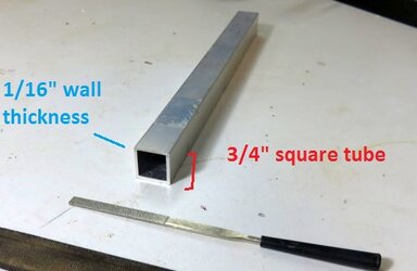
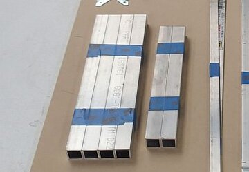
I find ¾” aluminum square tube with 1/16” thick wall a good size to work with for PC parts--strong and light. It is generally available at Home Depot and Lowe’s, altho I purchase from onlinemetals.com.


Stock%2Baluminum%2Bsquare%2Btube.jpg


6061 T6 ¾” .062 thick square tube aluminum.
https://www.onlinemetals.com/merchant.cfm?pid=18011&step=4&showunits=inches&id=1270&top_cat=60


Sometimes at Home Depot it's easier to find ⅛” thick wall thickness--this is fine, but 1/16” is thinner (thus lighter) and perfectly strong for its purpose.


Process for cutting square tube aluminum


I use 3 tools for cutting my square tube aluminum.


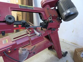
To actually cut the square tube, I use a chopping band saw. This is the perfect tool for this. Highly accurate, thin cut, like a knife through butter.


Chopping%2Bband%2Bsaw.jpg


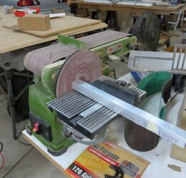
For a super nice, squared off finish, I use a disk sander.

Disk%2Bsander.jpg


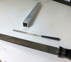
And files.

Files.jpg


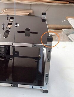
In my builds, a super nice finish isn’t necessary as I cover the ends with plastic end caps.

Plastic%2Bcap.jpg


However, this process is useful for finishing ends of aluminum trim that will be exposed.


Not many people are going to such a specialized tool as a cutting band saw.

Here are some alternatives:

Standard compound miter saw--most people access to one of these. With the right blade, it’ll cut this aluminum fine. Altho I used this method for years, I don’t really like it. It is violent! Make sure pieces you are cutting are well clamped on both side, and don’t be surprised by flying chips of metal.


Standard Bandsaw would be an excellent tool of choice.


Cut-off saw. This works great. It is loud and it generates a lot of heat in the pipe, so don’t burn yourself. Unlike a compound miter saw, a Cut-off saw’s blade does not have teeth, so the metal isn’t chipped away in a violent fashion.


If you haven’t got any power tools, I would recommend a hacksaw and a compound miter box. This seems somewhat unmanly, but don’t be deceived. Honestly, this might be my second choice behind my chopping band saw. It is highly accurate, safe, easy, and inexpensive.


You can try grinding at it with a dremel or a handheld cutoff. Just be sure to have a good plan to finish your ends--ie a disk sander or some other way to square off your ends nicely, or plastic end caps as shown above.
 
Last edited:
Thanks for the comments!


Main Structure: Posts
Finishing aluminum--the brushed look


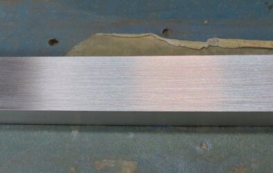
Sq%2Btube%2Bal%2Bcut.jpg

Now that we’ve got our square tube aluminum cut, this is actually the best time to apply a brushed finish--before we start bolting on brackets.


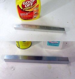
Step #1--Clean

Alu%2Bbrush%2Bclean.jpg

I use something like Goof off plus some isopropyl.


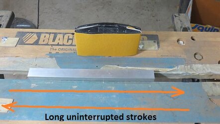
Step #2--Brush with coarser sand paper

I start with a 120 grit.

Alu%2Bbrush%2Bsand1.jpg

The technique is important. I’ve secured the piece in a clamp. Then I move my sanding block across the entire length (and past the ends) in one long uninterrupted stroke. The goal is to generate long parallel scratches. I will do something like 10 passes. The pattern should hide or fade any small dings or imperfections.


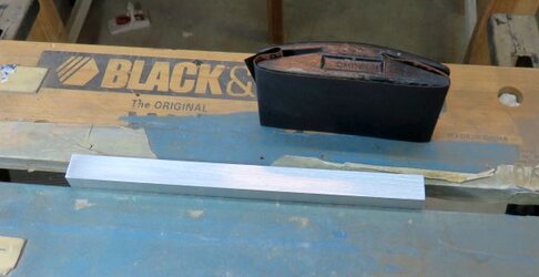
Step #3--Brush with finer sandpaper


I typically use 220 grit. It is important to use at least 2 different grits. The different in the coarseness of the parallel scratches gives it depth. It is also important not to do too many passes with the finer grit, as this will erase all the coarser grit scratches--I roughly do maybe 6 passes.


Alu%2B220%2Bgrit.jpg


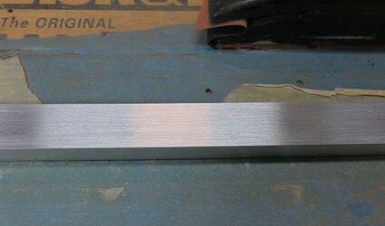
Step #4--Admire your work


Alu%2Bbrushed.jpg


Closer up:

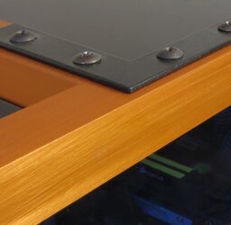
Alu%2Bbrushed2.jpg


Step #5--Go fancy!

If you want to go super fancy, you can have the brushed aluminum anodized, as I did with my Exoframe Mini Project:


Front%2Bleft%2Blo%2Blit%2Bbright.jpg


Alu%2BBrushed%2Baluminum2.jpg
 
Last edited:
Thanks!


Main Structure: Posts
Attaching brackets


The next step is to attach the mounting brackets to the main posts.


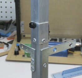
Mounting%2Bbrackets%2Bon%2Bposts.jpg

Each post has 4 L brackets mounted to it.


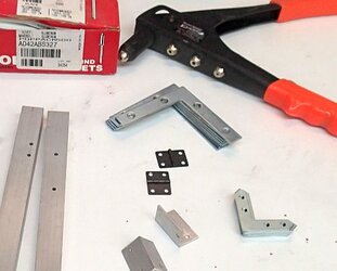
For the L brackets, I use these, but just about any will do. You may also see that I use some smaller L brackets, which I got at bulk for super cheap.

L%2Bbrackets.jpg


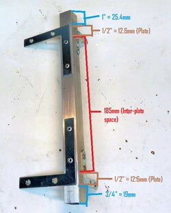
Here are the measurements for placement of the L brackets:

Post%2Bassembled%2Blabeled.jpg


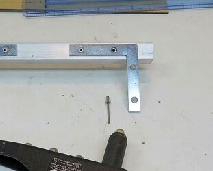
I use pop rivets to attach the L brackets to the posts. Pop rivets are great when you want a semi permanent means of attachment--also you do not need any sort of access to the inside of the square tube to rivet.

Riveting2.jpg


Couple of little animation I found on the internet to illustrate how it works.

http://www.technologystudent.com/joints/popriv1.htm


Step by step:
I place my brackets where I want them.
Then I mark the holes.
Using my previously described techniques for drilling a hole, I drill a ⅛” hole (I'm using 1/8" pop rivets, a standard size.
Then I place my L bracket in the proper location, and rivet them in place.


If you ever want to undo a rivet, simply use a ⅛” drill bit and drill right down the center of the rivet. This will knock the ball off and separate the rivet into 2 loose pieces.


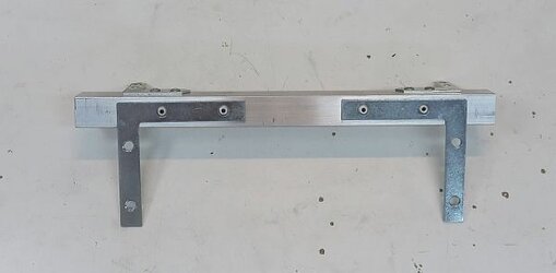
Post%2Bcomplete.jpg

Now you 4 base posts are complete.
 
Last edited:
Main Structure: Posts
Folding PCI brackets


The back 2 posts will also have hinged extensions to support the PCI bracket. As I mentioned earlier, I do this so that the PCI bracket can fold down.


PCI%2Bbracket%2Bflip%2Bup3.jpg


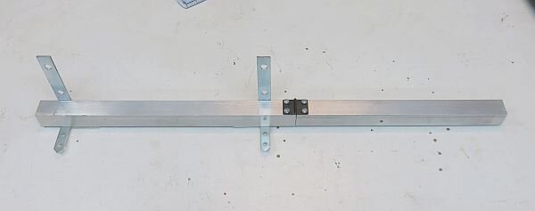
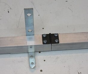
The first step is to attach the PCI bracket extension (210mm) to the base post with the hinge. I’ve got some small ¾” wide hinges, and I’m attaching them with M3 screws into threaded holes created in the square tube:


Posts%2Badding%2Bhinges1.jpg


Posts%2Badding%2Bhinges2.jpg


The next step is my mechanism to lock the hinge straight when you want it in the upright position.

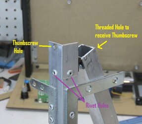
To do that, I fabricated a bracket from a short length of ¾” L channel (1/16” wall thickness).

Posts%2Bhinge%2Bbracket1%2Blabeled.jpg

Here, the bracket has been riveted to the end of the base post spanning the split at the hinge. There is a thumbscrew hole on the base unit, and a threaded hole to receive the thumbscrew on the upper extension.


When you swing the extension up, you can than lock into place with a thumbscrew:

Posts%2Bhinge%2Bbracket2.jpg

Makes a pretty solid connection.


And now the posts are complete!


Posts%2Bcompleted.jpg
 
Last edited:
Trim/Aesthetics
Finishing the Panels


Let’s make our panels look nice.

I like to use Polyurethane on my MDF panels. Looks nice and seals up the wood product (remember, MDF is very absorbent).


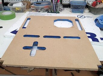
Here are some freshly completed unfinished panels:

Station14%2Bpanels%2Bcut.jpg


And here is what MDF sealed with polyurethane ends up looking like:

Station14%2Bcomplete2.jpg


Polyurethane seals the MDF, gives it a nice warm wood tone, and a nice shiny finish. This is my standard paint job.


But for some of my recent projects, I’ve been taking it a step further--adding some color:

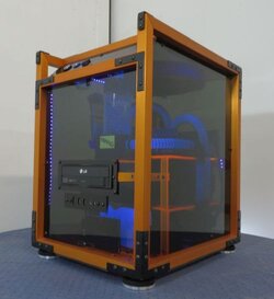
Station30%2Bfinal7.jpg


So here is my detailed step by step process...
 
Last edited:
Trim/Aesthetics
Finishing the Panels: the Navig treatment


There are so many different techniques for this paint job, and I’ve tried many and settled on this general method:

I apply my finish one side at a time (bottom side first, complete the whole paint process--then top side and complete the whole paint process)
Since I’m doing one side at a time, I use masking tape and mask of all of the edges of the side I’m not painting.
I use high-gloss polyurethane (and/or stain) from a paint can--and disposable foam brushes


Other methods I’ve tried:
I’ve finished the panels with spray-on rattle can polyurethane. The plus sides is that this method does not require tape-masking (which is a huge chore).

The downsides are:
The finish is not quite as smooth and glossy as paint-on polyurethane
It is very difficult to get the inside edges of the cable-pass thru slots
It is expensive--to get a decent finish I went through 3 or 4 spray cans

I’ve tried “quicker” products like rub-on polyurethane and combo stain-finish products. The problem is that MDF is very absorbent, so you actually need multiple coats. Rub-on just doesn’t come out very nice, and combo stain-polyurethane products becomes too dark if you apply multiple coats.

I’ve tried standing my panels on their side and painting both sides simultaneously to try to avoid the huge chore of tape-masking. However, I’ve found this causes drip-edges at the corners of the cable pass-thru slots.

So my approach to painting: take it slow, take your time, cut no corners, mask, and one side at a time.


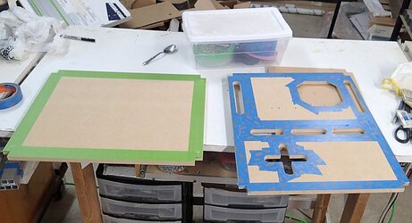
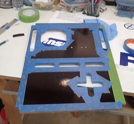
Step 1--Mask the top side


Paint%2Btape1.jpg
Why paint the bottom side/mask the top side first? Any accidents or drips can be sanded out of the top side before finishing it.

I apply masking tape along all edges where paint might drip: outside edges and along the cable pass-thru cutouts. I leave the inside walls of the cable pass-thrus unmasked (they are going to get painted during this round).

Make sure to seal the tape--I run a spoon along the edge--this activates the glue under the tape paper to form a paint proof seal.
 
Last edited:
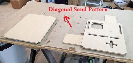
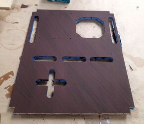
Step 2--Sand the bottom side


Panel%2Bfinishing%2Bmasking2%2Blabeled.jpg

*** See edit below*** I use 220 grit sandpaper on a rubber sanding block, and I like to make uniform diagonal passes. This is going to help add a little bit of a brushed look to the stain.
Sometimes if the MDF is real rough, I’ll do the other diagonal (making a sort of cross-hatch pattern), but always finish with the same diagonal.
Also carefully sand the inside edges of all the cutouts and pass thrus. I wrap little piece of sand paper around my finger and just work these edges.

***Edit***

For a smoother finish, particularly for the under-layers of polyurethane, I tried (and had better success) with the following sanding technique:
Short strokes, in multiple directions.

I tried short light strokes in one diagonal, then in the other diagonal, then in small circles, and finally in large circles. It is important to keep your sand paper clean also, otherwise built up sand-off with clog the paper and start introducing gouges.

I’ve also used a random orbit sander with vacuum ports. This really keeps the sandpaper from clogging. Use a light touch.


Step 3--Clean
Make sure to clean off the surface after sanding. I brush it, vacuum it, and then actually use a tack cloth.


Step 4--Apply pre-stain

Once again, MDF is very absorbent, so I feel like a pre-stain makes the stain come out much more uniform.
Let the pre-stain dry according to instructions.


Step 5--Apply the stain
I use a disposable foam brush and apply the stain.

Paint%2Bstain%2Bwith%2Bbrush%2Bfinish.jpg

I am using a stain called Cordova from Sherwin Williams. It is a very nice deep woody red.
After it has dried several minutes, I run a standard brush very lightly across the surface at the usual diagonal. This is going to add a very faint brushed/wood grain texture.
Let the stain dry according to instructions.
 
Last edited:
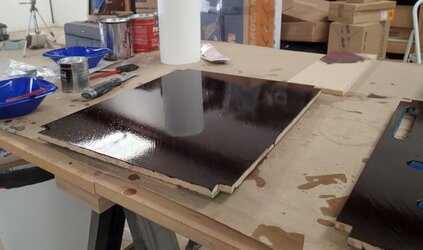
Step 6--Apply the first coat of high gloss polyurethane
I typically use fast dry oil based Cabot. I also use a disposable foam brush--technically you should use a natural bristle for oil based, but I get good enough results, and with much less hassle. Let the brush soak a little bit to minimize bubbles. Do not over brush as that will also cause bubbles.

Paint%2Bfirst%2Bpoly%2Bcoat.jpg

I apply one thin layer, stroking in the same diagonal as the sanding.
Let it dry completely as per instructions.


Step 7--Apply the second layer of high gloss polyurethane
No sanding after the first coat of polyurethane--often the MDF will soak up so much polyurethane, if you were to sand it, you might burn into the stain.
Apply as per step 6.


Step 8--Sand
After 2 coats of polyurethane, you should have enough coating in order to sand it down.
Sand the polyurethane just like Step 2.
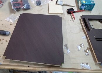
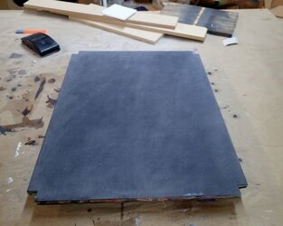
It takes a little bit of courage to take a pretty decent looking surface and sand it down, but as soon as you lay the next coat down, you can feel the difference. This is a what a sanded panel looks like:

Panel%2Bsanded.jpg

Don’t forget to remove the dust after sanding.


Step 9--Apply the third coat of polyurethane
You should notice that the polyurethane goes on really smooth and that you will only need a fraction of the volume compared to the 2 previous coats.


Step 10--Consider more coats then let fully dry
3 coats is usually sufficient--remember this is the underside.
Remove the masking tape and let dry thoroughly until fully cured.


Paint%2Bunderside%2Bfinished.jpg


And here is why you mask (and seal the masking tape)--stain will curl around the edges.

Paint%2Breason%2Bfor%2Bmasking.jpg


Now just remove your masking tape and start prepping for painting the top side.


.
 
Last edited:
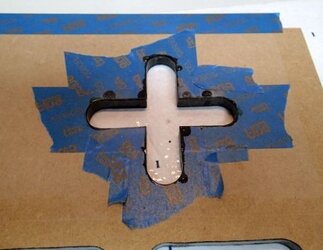
Step 11--Mask the bottom (just painted side)

Make sure your paint is fully dried and cured!


Paint%2Bmasking%2Bbottom%2Bside.jpg

This time, be sure to tape-mask the inside edges of the cable pass-thrus.


Step 12--Prep the top side.

As before, sand in a diagonal pattern, 220 grit, and clean thoroughly.

Paint%2Btop%2Bside%2Bprepped.jpg


Step 13--Apply pre-stain and stain

Once again, very lightly brush the wet stain.


Paint%2Btop%2Bpanel%2Bis%2Bstained2.jpg


Step 14--First 2 coats of Polyurethane

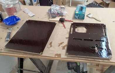
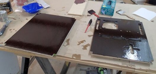
After the stain has dried according to its instructions, apply the first and second coats of polyurethane:


Paint%2Btop%2B2%2Bcoats.jpg
 
Last edited:
Sorry, it has been a while since my last post. Where have I been? Building another benching station, of course. Apparently, this post has drummed up interest, so I’ve been fabricating a new station. My experience with this new station and pictures will get incorporated into this thread.

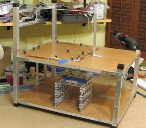
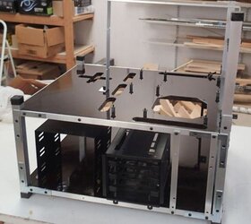
Station #31, built between the last post and this post:

Final%2Bpic13.jpg


Very importantly, finishing the panels on this station did not go well following with my own steps as detailed above.

So I am going to edit myself.

Just goes to show, I am by no means any “authority” on the matter, and I’m still learning all the time.

Sanding the unfinished panels went fine, most likely because any faults were hidden by the application of stain as well as the the “brushing-in grain” technique.

However, when I went to sand the under-layers of polyurethane, the continuous diagonal strokes introduced long gouges that remained after application of the next coat. Could it be the change in weather (affects drying time, also, this customer requested a semi-gloss finish instead of a gloss finish), could it be the sandpaper? I don’t know.

If a smooth finish is desired, I would try the following technique.


New Sanding Technique

Short strokes, in multiple directions.

I tried short light strokes in one diagonal, then in the other diagonal, then in small circles, and finally in large circles. It is important to keep your sand paper clean also, otherwise built up sand-off with clog the paper and start introducing gouges.

This produced a much better finish.

I’ve also used a random orbit sander with vacuum ports. This really keeps the sandpaper from clogging. Use a light touch.
 
Last edited:
Back