• Welcome to Overclockers Forums! Join us to reply in threads, receive reduced ads, and to customize your site experience!

FEATURED Buidling a Benching Station Navig Style

Overclockers is supported by our readers. When you click a link to make a purchase, we may earn a commission. Learn More.
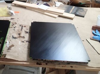
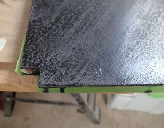
Streaky finish:

Streaky%2Bfinish.jpg


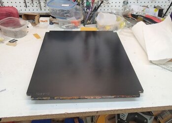
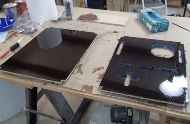
Nice finish:

Nice%2Bfinish.jpg

- - - Updated - - -

Step 15--Sand with 220 grit

Recap--I put down the first 2 coats of polyurethane on the top sides of both panels

Now sand with 220 grit, using my short strokes technique.


Step 16--Add the ghost logo

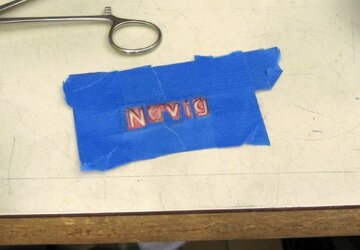
Long time back,I made a stencil with my logo.


Logo%2Bstencil%2Bset.jpg

It’s kind of ghetto, I literally cut and taped together stencil letters from the craft store.


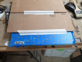
I positioned my stencil, masked off the rest of the panel:

Stencil%2Bapplied.jpg


And then with a light touch of spray-can metal flake, add my logo:


Ghost%2Blogo%2Bapplied.jpg

It looks really faded against the sanded background, but it will POP when the final top coats are applied.

- - - Updated - - -

Step 17--Apply the final coats of polyurethane (one or two)

Here are some nice finished pictures.

Glossy coat going down on my personal station:

Paint%2BTop%2Bcoat%2Bfinished.jpg


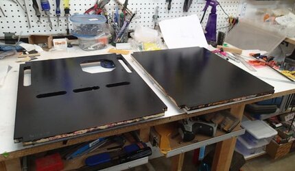
Semi-gloss coat on my most recent build:

Final%2Btopcoat.jpg


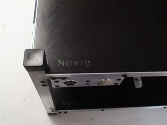
And the ghost logo, after the finished coats have been applied.
Ghost%2Blogo%2Bfinished.jpg
 
Last edited:
Bracketry

Brackets may seem a little boring, but really, what is a benching station besides a bunch a brackets for holding your components in place?


PCI bracket

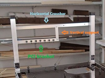
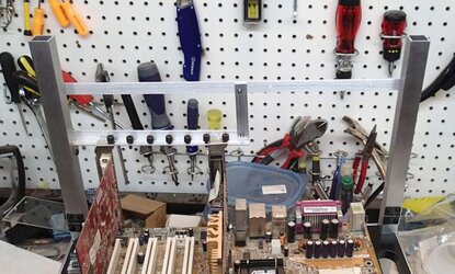
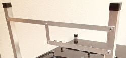
This is my PCI bracket system. It’s a little elaborate, but I like to have it well supported.

Brackets%2BPCI1%2Blabeled.jpg


There are three components:

Actual PCI bracket--made from ½” aluminum angle bracket (1/16” thickness), length is 200mm
Vertical Support--made from ½” bar (1/16” thickness), cut to 65mm
Horizontal Crossbar--made from ½” bar (1/15” thickness), cut to 365mm


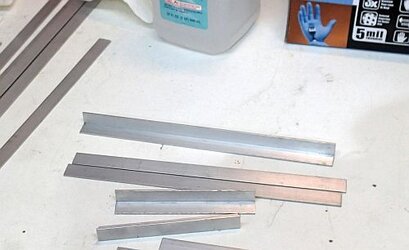
To fabricate the PCI bracket component, I started with a stock piece of ½” angle bar cut to 200mm.

Brackets%2BPCI%2Bstock.jpg


Brackets%2BPCI2%2Blabeled.jpg

In order to mate properly to the post, this red portion here needs to go away, or as I do--get bent.


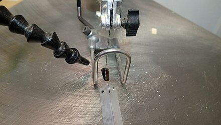
First I cut the down the center line with by scrollsaw to the length of ½”.
(Actually, first I put in some mounting holes which you can see--its easier to do this prior to bending)

Bracket%2BCutting%2Bpci%2Bbracket.jpg


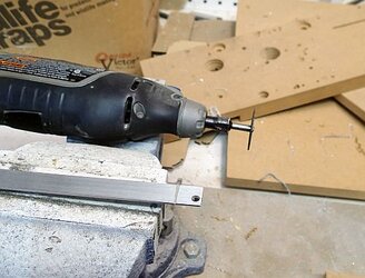
Then I scored my bend with my dremel.

Bracket%2BCutting%2Bpci%2Bbracket2.jpg


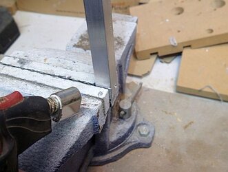
Clamp the piece into my vice, add a little heat, and bend.

Bracket%2BBending%2Bpci%2Bbracket.jpg


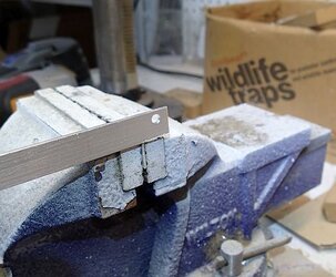
Brakcet%2BBending%2Bpci%2Bbracket2.jpg


Bracket%2BBending%2Bpci%2Bbracket3.jpg
 
Last edited:
Thanks so much!


Next step is to mount the bracket.

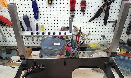
Seen here from the back, the bracket mounts to the post thru the holes I made earlier.


Brackets%2BPCI%2Bfrom%2Bback%2Blabeled.jpg

If you’ve been following my motherboard measurements for placement of the motherboard mounting holes, then mounting it to the backside of the post should put it in the proper location to interface with PCI cards.

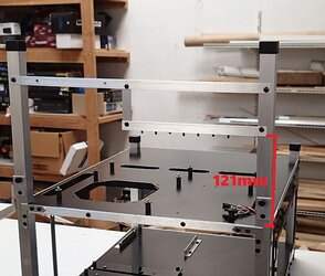
If you are using the standard ½” mobo standoffs, then the bracket should be mounted at a height of 121mm.


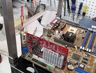
It’s always best to actually mock-up mount motherboard and a PCI card to confirm placement.


Brackets%2BMarking%2Bpci%2Bbracket%2Blabeled.jpg

At this time, I also marked the location of the first PCI bracket mounting hole (red arrow).


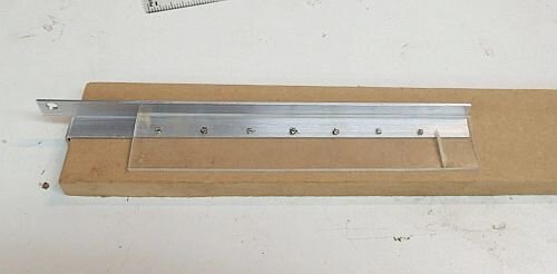
To make the rest of the mounting screw holes, I use a jig.


Bracket%2BPCI%2Bholes.jpg

The space between each hole is 20.3mm.

The center of the hole is 2.5mm from the edge.

I make the holes in the method I’ve outlined before, with a #36 drill bit and a 6-32 tap.


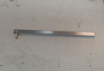
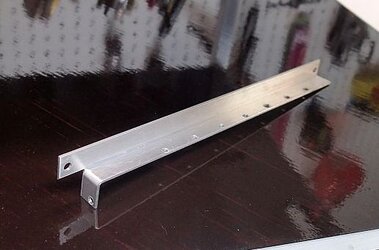
And here is my nicely crafted final PCI bracket


Bracket%2BFinished%2BPCI%2Bbracket.jpg


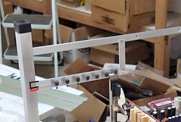
After remounting the PCI bracket, the next step is to mount the Vertical Support Bar and the Horizontal Cross Bar.

Be sure to use a square and a level!


Bracket%2BMounting%2Bpci%2Bbracket2.jpg

Vertical Support bar mounted with ⅛” rivet.


Bracket%2BMounting%2Bpci%2Bbracket3.jpg

Horizontal Crossbar completes the structure.


Top it off with a set of 6-32 thumb screws.


Bracket%2BMounting%2Bpci%2Bbracket6.jpg

And that is how I support my PCI cards.
 
Last edited:
Bracketry

Hard drive racks


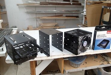
I’ve used a number of different style pre-fabricated hard drive racks, mostly surplus units from actual cases.


Hard%2Bdrive%2Boptions.jpg

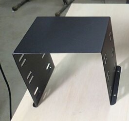
In the middle is the standard--essentially slotted bent sheet metal rack.

On the right is the fan-assembly unit (for conversion of 5.25 bays).

My favorite is on the left--some inexpensive Corsair units, with plastic bracket-mounts that slide into a metal cage.


My DIY Hard Drive Bracket System

However, supplies of these sorts of units has dwindled, so it was time I designed my own DIY unit or system so that I wouldn’t have to rely on outsourcing.

I actually made a whole independent thread when I developed this:

http://www.overclockers.com/forums/showthread.php/601153-DIY-hard-drive-rack-ver2


The basic principle is this:

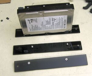
The hard drive mounts to a hard drive caddy, which is essentially a slab of plastic with some properly placed countersunk holes.

Hard%2Bdrive%2Bcaddies1.jpg


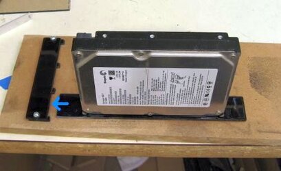
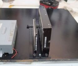
The bracket-mount then slides into a hold-down unit.

Hard%2Bdrive%2Bcaddies2.jpg


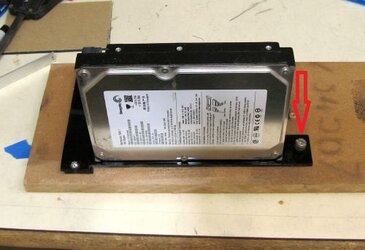
Then the bracket-mount gets locked down with a thumbscrew.

Hard%2Bdrive%2Bcaddies3%2Blabeled.jpg
 
Last edited:
Let’s go into more detail.


Hard drive caddies


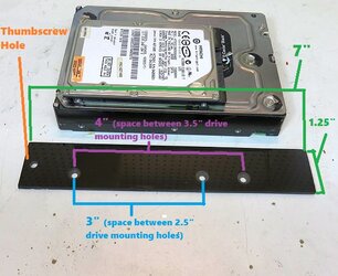
My hard drive caddies are 1 ¼” wide and 7” long and are made of ⅛” acrylic.

In this picture I’ve labeled the holes in each piece and their relative distances.

Hard%2Bdrive%2Bcaddy%2Bmeasured.jpg

The hard drives mount to caddies with 6-32 (3.5” size drives) or M3 (2.5” size drives) screws.

The screw holes are countersunk, that way when the drives are mounted, the caddies can slide around without any screw heads dragging.


Hold down unit

The hold down unit is just another rectangle of plastic, I usually go with ½” wide--the length is variable based on how many hard drives you want--I’ve done as few as 2 and as many as 10.


Hard%2Bdrive%2Bhold%2Bdown%2Bunit2.jpg

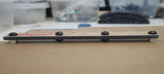
There are holes drilled at the exact centers of the spaces between the hard drive caddies (I typically space them at ¼”).


Hard%2Bdrive%2Bhold%2Bdown%2Bunit1.jpg

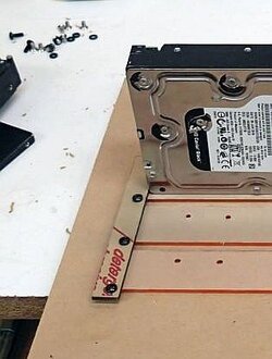
The holes have screws (6-32) with spacers (in this picture 2 aluminum and 2 rubber) to guide the hard drive caddies into place.


Then to lock the the caddies in place, I use 6-32 thumbscrews. To receive the thumbscrews, I merely install 6-32 brass threaded inserts right into the appropriate location of the panel.

I’ve previously described use and installation of threaded inserts here.


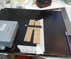
Here you can see I’m planning out the location of everything, and the threaded inserts have been installed:

Hard%2Bdrives%2Bprepping.jpg


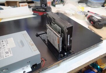
And here I’ve gotten everything installed:

Hard%2Bdrives%2Bmounted.jpg

This customer only wanted a 2 drive rack.

If you look closely, I’ve also installed an additional guide post, just helps slide the caddies into place easier.


As I’ve mentioned this system is easily scalable:

Hard%2Bdrive%2Bsix.jpg

Here is a six drive rack.
 
Last edited:
Bracketry

5.25 Bay rack


Once again, when available, I’ve used prefabricated racks.

5.25%2Bdimastech.jpg


However, these days, most people really only want a single unit.

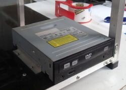
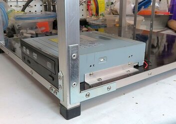
So an easy way to bracket in a 5.25 drive like an optical drive, is to use a pair of ½” aluminum angle bracket, cut to 100mm, with some appropriately placed mounting holes.


5.25%2Bbracket1.jpg


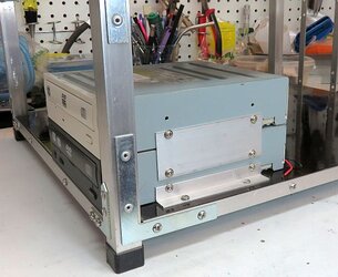
Mounting a 5.25 unit is as simple as sliding it into place, and screwing in the mounting screws (M3 sized):


5.25%2Bbracket2.jpg


If you want more 5.25 bay units, and you can’t find a prefabricated unit, then you can add a pair of simple side brackets, made from 1 ½” aluminum rectangle (1/16” thickness, cut to 100mm), and mount one 5.25 bay unit onto the next, stack-style.


5.25%2Bbracket3.jpg
 
Last edited:
Bracketry

Power Supply Bracket


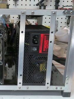
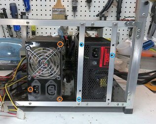
Simplest method for constructing a sturdy power supply bracket is to use two strips of ½”, 1/16” thick aluminum bar, mounted at the width of a power supply:


PSU%2Bbracket%2Blabeled.jpg

The locations of the mounting holes are NOT symmetric--2 holes are offset from each axis.
So, in my bracket set, only 3 mounts are used at a time (which is plenty to secure to PSU), and the locations are dependent on which side the power supply is lying on.
So to accommodate a PSU on either, side, you have to make 6 holes.
 
Last edited:
Great thread! :thup: I still have the navig-built benching station I won years ago in the rosetta@home contest and I love it for playing around with spare hardware, really good quality here.
 
Thanks! Figured it was about time to brain-dump what I have learned about making stations, altho this thread is ridiculously long. Hang in there, tho, almost complete!


Bracketry

Switch Panel


I’ve always enjoyed building switch panels for my PC projects. I’m not sure why. It's probably a combination of things:
Not technically difficult.
But details matter a lot.
There is a lot of choice, even down to which buttons you choose.
The end result is easy to appreciate, not only visually, but tactile-wise.


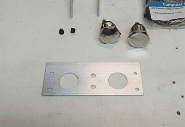
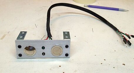
Here are my starting components for a standard switch panel:


Panel is made from 1 ½” aluminum bar, 1/16” thick, 100mm long
https://www.onlinemetals.com/merchant.cfm?pid=17863&step=4&showunits=inches&id=1279&top_cat=60

1 chrome vandal momentary switch, domed--for the Power-On button
http://www.allelectronics.com/item/pb-143/hd-metal-pushbutton-n.o.-momentary/1.html

1 chrome vandal momentary switch, flat--for the Reset button
http://www.allelectronics.com/item/pb-144/hd-metal-pushbutton-flat-momentary-n.o./1.html

2 LEDs (the client opted from green for power on, white for HD-activity), I’m using T1 (3mm)
http://www.goldmine-elec-products.com/products.asp?dept=1090

2 3mm LED holders
http://www.allelectronics.com/item/hled-5/clips-for-t-1-3mm-leds/1.html

2x ½” wide, angle brackets
https://www.mcmaster.com/#1556a63/=17y39v2

Switch panel kit, I use this kit from Star Tech
https://www.startech.com/Computer-P...ries/ATX-Case-Front-Bezel-Wire-Kit~BEZELWRKIT

Some screws and rivets

Your tools and materials for sleeving cables


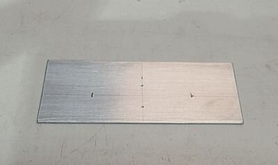
First step was to mark my layout:

Switch%2Bpanel%2Blayout.jpg


And then to make my holes.

Switch%2Bpanel%2Bcutout.jpg

The 4 holes on the outer edges are to mount the angle brackets--I will be using ⅛” rivets, so these holes are ⅛”.

The larger holes are for the chrome buttons--they are somewhere shy of ¾”. To make these holes I used a unibit.

The middle holes are 3/16” to fit the LED holders.

At this time, I also put in my brushed finish.


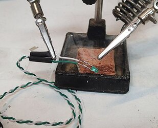
Switch%2Bpanel%2Bsolder%2Bleds.jpg

Next I changed over the stock LEDs to my custom set. Old school soldering!


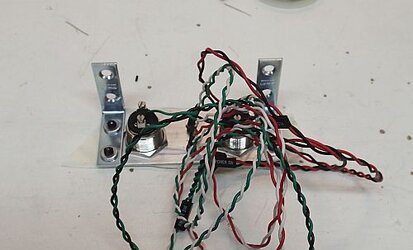
Switch%2Bpanel%2Bbackside.jpg

Time to hook up all my cables.

The buttons have a thread hole with a screwdown. Since the wires are such thin gauge, I strip the ends, fold them back to double up the thickness, then solder the ends solid.

A single goop of hot-glue holds the LEDs in their holders quite well.


As you can see, this is a real rat’s nest of cables, so a bit of sleeving, and here is the finished product:

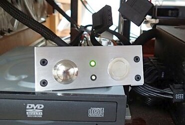
Switch%2Bpanel%2Bcompleted.jpg


Always important to test the functionality before releasing it to the wild:

Switch%2Bpanel%2Btested.jpg


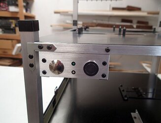
And here it is mounted in its final destination:

Switch%2Bpanel%2Bmounted.jpg
 
Last edited:
Bracketry

Miscellaneous Brackets--The Brollocks Fan Bracket


When I was constructing Station #6, the client wanted a bracket that could fans over various parts of the motherboard. So he sketched out a concept. It became so popular that I would say more than half the time clients want it. I give you the Brollocks fan bracket.


Brollocks%2BStation6%2BCustom%2Bbracket1.jpg

This is a picture from 2008 of the first Brollocks bracket.


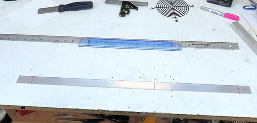
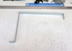
First I start with some stock metal bar. It is 1” wide, 1/16” thick, 625mm in length.

Brollocks%2Bstock.jpg

I’ve also laid out my plan. The 3 pink lines are where I will bend the metal. On each end are mounting holes for thumbscrews. And all along the length are locations to mount 120mm fans.

The pink lines/ bends come at 40mm (each measurement is + ~0.5mm to account for the radius of the bend) (and measuring from the left end of the picture above), 370mm and 592mm.
The first segment is the rise up from the PCI bracket (40mm), the next segment is to clear the distance over the motherboard (330mm), the third segments is the drop down to the panel (222mm), and the final segment is the foot to allow for a thumbscrew mount to the panel (30mm).

The fan holes I locate by eye, and I use the fan grill above to get the inter-hole distance spot on.


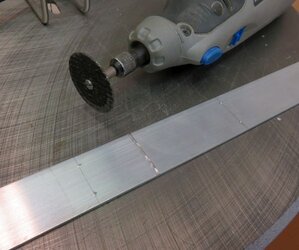
On the 3 lines where I plan to bend the metal, I will actually take my dremel and make a score. This will help make the bend much easier, more controlled, and more accurate.

Brollocks%2Bdremel%2Bscore.jpg


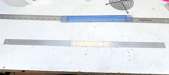
I also take this time to drill out all the mounting holes. You can do this later, but it is easier to do while the piece is still flat.
Also this would be the time to do any sort of finish work such as adding the brushed finish.

Brollock%2Bready%2Bfor%2Bbend.jpg

The aluminum trim has the bend lines scored, and the fan holes drilled.


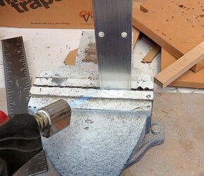
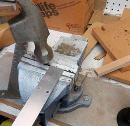
To make each of the 3 bends, I first carefully mount the piece in my vice, with the score line centered, and the piece perfectly perpendicular to the vice.

Then I add a little heat with a butane torch.

Brollocks%2Bheat.jpg


Then I bend the aluminum, with a little “coaxing” with a hammer if necessary:
(use a block of wood with the hammer if you want to preserve a nice brushed finish!).

Brollocks%2Bbend.jpg


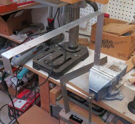
Continue bending each of the 3 locations.

Brollocks%2Bbend2.jpg


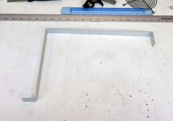
And here is the completed bracket:

Brollocks%2Bcomplete.jpg


Final mounting will technically have to wait until the station is essentially fully assembled, but this is how it will go:

At this end I add a threaded hole in the PCI bracket crossbar.

Brollocks%2Bthumbscrew1.jpg


On this end, I added a threaded insert into the deck of the panel.

Brollocks%2Bthreaded%2Binsert.jpg


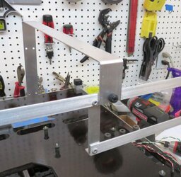
Mounts up with 2 thumbscrews.

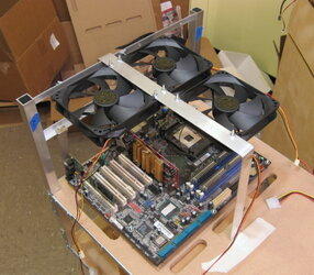
Brollocks%2Binstalled1.jpg

Brollocks%2Binstalled2.jpg


Fans can be mounted in any of the positions to get active cooling to whatever part of the motherboard you might need.

Brollocks%2Bfan%2Binstalled.jpg
 
Last edited:
Well, give me some time to start rebuilding my thread here thanks to Photobuck($)sit. This thread alone has close to 200 photos I've now got to re-host.
Apologies, Navig
 
Yup, not happy.

Looks like my new method (Google blogger.com) is working, so I will be working my way from the start, re-hosting all my pics.
 
Alirghtythen! Got all the pics re-uploaded, so on we go!
 
Bracketry

Miscellaneous Brackets--Radiator Mounts


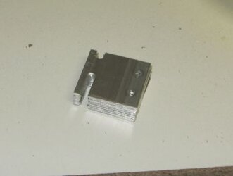
I developed a simple bracket to mount radiators. It’s kind of ugly, but it does mount just about any size of radiator, even with different inter-fan spacing.


Brackets%2Brad1.jpg

The 2 holes are for mounting to the station. The slots are for fixing to a radiator while accounting for different inter-fan spacing from different watercooling companies.


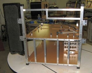
Most of my clients have requested these brackets mounted what I call “Wing-style”.

Brackets%2Brad2.jpg


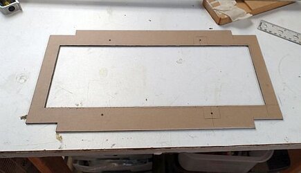
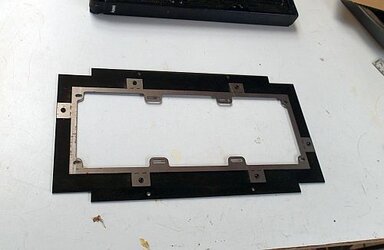
Recently, I designed a radiator shroud, involving laser cut panel.

Here is the link to my thread when I developed it.

http://www.overclockers.com/forums/showthread.php/722236-Custom-Radiator-Shroud-Navig-Style

http://www.theraptorpit.com/forum/i...y-first-attempts-at-a-custom-radiator-shroud/


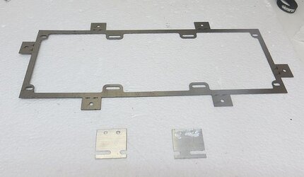
Brackets%2Brad7.jpg


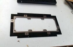
The bracket was laser cut from 20 gauge stainless steel--it is specifically for 3x120 radiators, but can accommodate just about any brand.


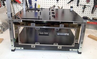
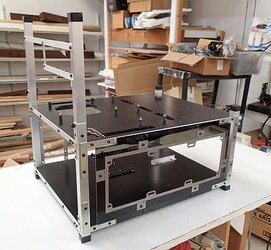
My latest client’s station was a bit “classier” than my rough stations and when he expressed interest in a 3x120mm radiator mounting system, I incorporated this bracket into a plastic panel to mount to the side of the station, bit of a nicer looking mounting system.


Brackets%2Brad5.jpg

Plastic portion


Brackets%2Brad6.jpg

Assembled.


Mounts to the side of his station:


Brackets%2Brad4.jpg


Brackets%2Brad3.jpg

I have devised all kinds of different brackets thru the years. Just wanted to showcase a few really commonly requested ones--really the only limit is imagination.

Looks like that is it!

On to final assembly...
 
Final Assembly

Step 1
Prep the panels


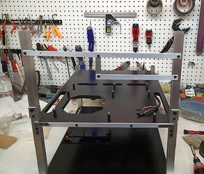
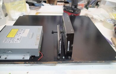
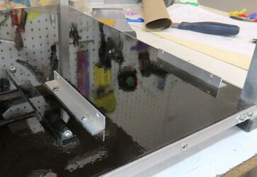
It's actually easier to attach stuff to the panels while they are disassembled, so I’ve started with the 5.25 mounts and the hard drive mounts. Most of this stuff can be mounted anywhere, so some thought must go into the final layout.


Ready%2Bbottom%2Bpanel.jpg


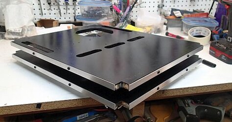
Here I’ve attached the brushed aluminum trim to the sides of the panels:

Panel%2BTrim%2Battached.jpg


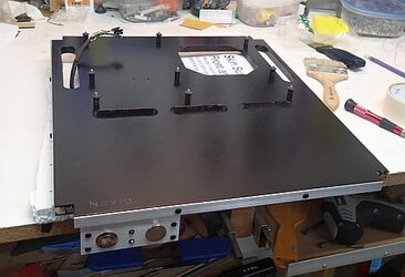
Added the switch panel and motherboard standoffs.

Panels%2BTop%2Bpanel%2Bprepped.jpg

Panels = Ready


Posts


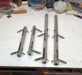
We’ve got our posts constructed.

Posts%2Bbuilt.jpg

Posts = Ready


Brackets

We’ve finished our brackets.

PCI:

Ready%2Bpci.jpg


Hard drive

Ready%2Bhard%2Bdrives.jpg


5.25 bays

Ready%2B5.25.jpg


PSU:

Ready%2BPSU.jpg


Switch:

Ready%2Bswitch.jpg


Miscellaneous
Brollocks Fan Bracket

Ready%2BBrollocks.jpg


Radiator Bracket

Ready%2Brad.jpg


Brackets = Ready


On to final assembly.
 
Back