• Welcome to Overclockers Forums! Join us to reply in threads, receive reduced ads, and to customize your site experience!

FEATURED Buidling a Benching Station Navig Style

Overclockers is supported by our readers. When you click a link to make a purchase, we may earn a commission. Learn More.

Navig

Senior Case Master
Joined
Dec 7, 2003
How to Build a DIY Benching Station--Navig Style


Station27%2Bcomplete2.jpg


I recently got a request to build a DIY Navig Benching Station. Between standard and some (very) non-nonstandard builds, I’ve constructed over 40 different stations over the last decade.


Since the requested station is pretty much a standard build, I figured I’d take the time and the pictures to summarize how I build my stations.


I’ve had an ongoing thread for some time, but I figured it was time to lay out a detailed blueprint as of 2016--I want to provide both approach/theory as well as a step by step construction guide.

Now that I have completed this thread, I am going to stick a link to my Hyperlinked Table of Contents.

- - - Updated - - -

What is a DIY Benching Station?


First things first, if you are new to Benching Stations, a quick primer.

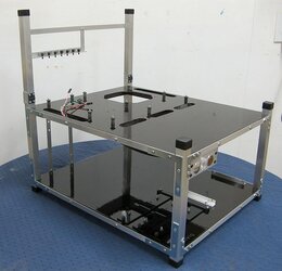
I would define a benching station as a structure to mount PC hardware to, but leave maximal access to the components.

Having your components out in the open makes it much more convenient to visually inspect and tinker with the components. The downsides of a benching station include the lack of protection, dust, and noise. A lot of people do their benching by just laying their components on a table yard-sale style, but I like having my stuff hard-mounted to something.

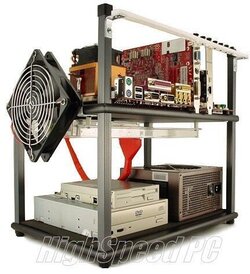
Plenty of companies make stations--the classic station that inspired me is still readily available.


Tech%2Bstation.jpg


I took one look at this, and understood its utility, but I was like “Hey, I bet I could build one of those!” So that was the “DIY” inspiration. To build a benching station from junk readily available from the local hardware store.
 
Last edited:
Getting Started--Materials and Tools


Most of my materials and tools are available at your local Home Depot/Lowe's local hardware store.
I also do a fair bit of purchasing (and thus, will provide links) to Mcmaster Carr's.


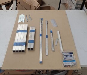
Here are most of my starting materials.


Station30%2Bmetal%2Bcut.jpg


I use a combination of wood (specifically MDF) and metal. I will go into much more detail as I construct the station.

The metal components are:

1) Aluminum ¾” square tube, 1/16” wall thickness.
(This material is available at most local hardware stores. I order it from onlinemetals.com, specifically 6061 aluminum.)

2) Trim pieces of ½” (1/16” thickness), 1.5” (1/16” thickness).
(This is also usually at the same area as the square tube, or navigate the menu in the link above to 6061 flat bar.)

3) I’ve got some zinc-coated steel L brackets and angle brackets.

4) I’ve got kit for replacing your power, reset, power-LED, HDD-LED wires. Specifically, I use:
https://www.startech.com/Computer-P...ries/ATX-Case-Front-Bezel-Wire-Kit~BEZELWRKIT

5) Not pictured, I’ve got 2 momentary vandal-style buttons, and 2 LEDs.
For my power button I use this:
http://www.allelectronics.com/make-a-store/item/pb-143/hd-metal-pushbutton-n.o.-momentary/1.html
And for my reset button I use this:
http://www.allelectronics.com/make-...d-metal-pushbutton-flat-momentary-n.o./1.html
A variety of buttons and switches can be found at various electronic sites and stores--you can definitely shop performance-pcs:
http://www.performance-pcs.com/switches
Just be sure, the switch action for Power-on and Reset is momentary (momentary switches close the circuit only while you are depressing the switch--as opposed to a toggle action).

6) LEDs can be found just about anywhere. Pick a cool color.

Also necessary will be various fasteners--ie screws and rivets.


Tools:
Most basic tools necessary: drill/driver (set of bits), jigsaw, hacksaw with a miter box, metal center punch.
I will go into more details about tool selection in each sub-section, with a comprehensive list at the end.
 
Last edited:
Construction Approach


I find it useful to break down my build into 3 categories:

1. Main structure
2. Trim/aesthetics
3. Hardware mounting bracketry


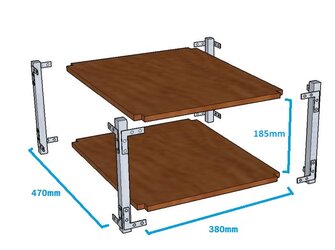
The general construction of my stations consist of 2 panels/plates (top and bottom) and 4 posts at the corners to hold them together.


Bars%2Bn%2BPlates1.jpg


Main Structure: Panels


Step #1
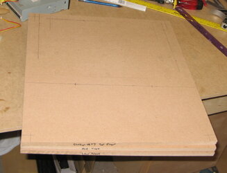
Cut the panels to size


Station17%2Bplates%2Bcut.jpg


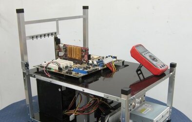
The size of the plates are 470mm x 380mm. I selected this size based on the top tier having a standard ATX motherboard, cable pass thrus, and space in front to hold a standard digital multimeter.


Wtih%2BDMM2.jpg


The height in between the plates is 185mm, which I based on having a power supply on its side + some generous room for cable management.


Bars%2Bn%2BPlates1%2Blabeled1.jpg


A side note on measurements. I will mix my fractional and metric measurements all the time. If you live in the US like I do, parts mostly come in fractional (ie inches etc) measurements. But generally speaking, metric units just work better with math. It’s just the way it goes. Have handy list of quick conversions and/or google nearby.


For my plates, I use ½” thick MDF, available at most hardware stores as “project board”. MDF is a nice artificial wood material because it acts like wood but has no grain (so it cuts smoothly in any direction). Also, it really doesn’t do much expanding/contracting like natural wood (also because of lack of grain), which is important whenever you are mating metal parts to wood parts. One of the downsides of MDF is that it doesn’t like water much--its pretty much a sponge. So my stations all get sealed with polyurethane (see my section in Trim/Aesthetics regarding paints/finishes). Another downside is that cut edges are pretty ugly, which is why I use aluminum trim pieces.

½” plywood is also an excellent material, but you will also have to deal with prettying up cut edges--also MDF is cheaper.


Tools for cutting your wood panels

For large panel cutting, your first consideration would be the store from which you are buying the panels (ie Home Depot or Lowe’s)--they will cut it to size for your for free. Just remember their accuracy may be off. If you ask, tho, they will make sure both panels are trimmed to the exact same size.

For cutting your own panels, the standard go-to would be the table saw. Just please use all the appropriate safety equipment, in particular a push-stick. I still find the accuracy of the standard table-saw to be off by a 1-2mm.

My choice tool for panel cutting, and as a general rule replacing most basic functions of a table saw, a tracked plunge cutter. Specifically, I use a Festool TS55. The way these tools work is, you put your panel on a sacrificial table (I use a sheet of rigid insulation). You put your guide track down and line up the straight edge with the edge you want cut (zero clearance). Then you put the track saw on the track, pull the trigger, plunge the blade into the material, and then just walk the saw along the guide track. I can’t express how easy, safe, and accurate this saw is.


Cutting%2Bplastic%2Bpanels.jpg

Other notes about the tracksaw--you can adjust depth, speed of blade, and angle. Measure twice cut once. In particular you must account for which side of your line you want to put the blade (ie accounting for the thickness, or kerf, of the blade, which is about 2.4mm thick). I’ve also attached a shop vac to the vacuum port, which sucks up virtually all the generated dust.


A circular saw with a straight edge clamp will also work well--tracked saw gives you more stability and convenience.
 
Last edited:
Main Structure: Panels


Step #2
Notch the corners of the panel


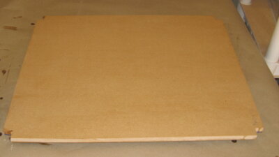
The shape of my plates are simple rectangles (once again 470mm x 380mm), with the corners cut out.

The notched corners allow my aluminum square tube posts to sit flush with edges of the plates.

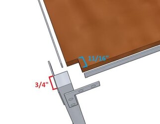
I use ¾” square tube aluminum (see section below on the post construction), so the cutouts would be ¾” in length on each side….
Except that I end up using 1/16” thick trim pieces to finish the edges of my plates.
Therefore to make the posts flush, the cutouts in the corners of the plates are ¾” - 1/16” = 11/16” on each side.


Corner%2BNotch%2Blabeled%2Bsmaller.jpg


Here I’ve notched the panel corners:


Station25%2Bplates%2Bpainted1.jpg


Tools for cutting the corner notches


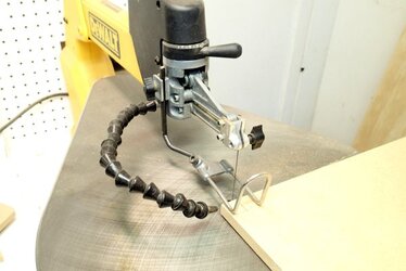
Personally I use a scrollsaw, just because I use one a lot and it’s ready to go


Scrollsaw.jpg


Standard tools would be a jigsaw or a bandsaw.
 
Last edited:
Main Structure: Panels


Step #3
Locate your motherboard


The next step is to drill the holes for the standoffs for the motherboard.

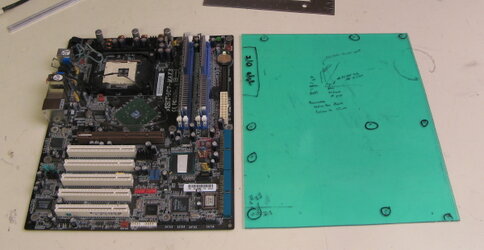
The easiest way to mark the motherboard standoff locations is to just plop your motherboard down where it needs to be, and trace out the little mounting holes with a skinny pencil or pen.

Since I do a lot of scratch builds, I took the effort last decade to make a jig, which I still use to this day:


Mobo%2Bjig.jpg


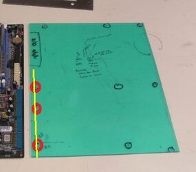
I’m going to highlight this important reference line here:


Mobo%2Bjig%2Blabeled.jpg


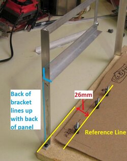
To locate my motherboard on my plates, I use this measurement::


PCI%2Bframe%2Blabeled%2B1.jpg


This rule takes a little bit of thinking, but it is important because the relationship between the PCI bracket and the motherboard is set.

If, like me, you are using a ½” angle aluminum as your PCI mounting bracket
AND
the back side of the PCI mounting bracket is exactly vertical above back edge of the panel
THEN
the reference line (thru the bottom left holes of a motherboard) should be 26mm from the back edge of the panel.


HOWEVER

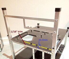
I’ve mentioned this before, but the way I’m constructing this station, I’m using pieces of aluminum trim to edge my panels, so for this station, must reference line should be:
26mm - 1/16 inch = 24.4mm from the back of the panel.

By the way, trying to measure 0.4mm accurately is not really reasonable. This whole build has tolerances of 2-3mm. But it's best to shoot being as accurate as possible.


PCI%2Bback%2Bmeasurements%2Blabeled.jpg


At this point, I physically draw in the reference line at 24.4mm in from the MDF edge.

Then I can put my jig, or the actual motherboard, and make sure I can see the reference line thru the 3 highlighted motherboard holes, and I know I’m good for alignment in this axis.
 
Last edited:
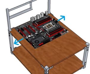
The next step is to center the motherboard on the width of the panel:


Centering%2Bmobo.jpg


This can be done by eye, remembering to keep the Reference Line visible thru the 3 designated motherboard holes.


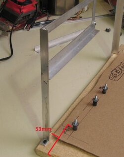
Or alternatively, the nearest-to-the-lower-edge motherboard hole of the Reference Line should be 53mm from the panel edge:


Motherboard%2Bedge%2Bmeasure.jpg


Locating the motherboard recap:

1) Draw your Reference Line (either 26mm or 24.4mm from the back edge of the panel).

2) Locate the bottom left Motherboard Hole 53mm from the edge.

3) Line up your motherboard or jig, keeping the other holes in line with the Reference Line.

4) Mark off all the rest of the Motherboard Holes.

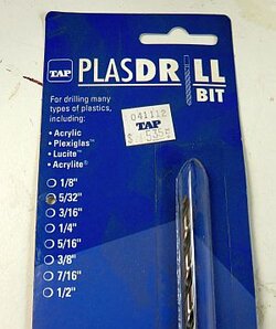
5) Drill the Motherboard Holes with a 5/32 inch drill bit.
 
Last edited:
Side note on Holes and Screws

By specifying the 5/32” drill bit, I’ve touched on the subject of drilling holes and screws, so I want to take a moment on the side to talk about drilling holes and screws. At first I didn’t think there’d be that much to say, but this section has grown into a giant book chapter!


[COLOR="#FFFFOO"]
Tools for drilling a hole (Drill, duh)[/COLOR]


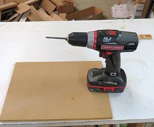
Cordless drill:

Drill%2Ba%2Bhole%2Bin%2Bwood1.jpg

Just about everybody’s got one, so it is the standard go to.


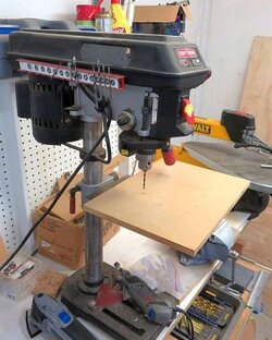
Drill Press:

Drill%2Ba%2Bhole%2Bin%2Bwood3%2Bsmaller.jpg


One of the first purchases I made when I started getting into modding (and woodworking) was a drill press. You might think that such a tool isn’t necessary cause you’ve already got a cordless drill, but I think this is one of the best $70 purchases I’ve made. The accuracy of a drill press in placement of a hole as well as angle of the hole is incredibly superior to a hand tool. And when it comes to modding, often times being off by 1mm is significant. Hand drill tends to walk along the surface of what you’re drilling which either misplaces your hole, or scratches your surface.


Portable drill press thingy: you can beef up your hand drill for $15, but it’s awkward compared to a drill press.


Drill bits

A standard kit of drill bits in the US comes in fractional inches--a 5/32” drill bit makes a hole 5/32” in diameter. As you get smaller, some more specialized kits switch to “Gauge sizes”, which allows for finer differences in size. For example, later on I will refer to a No. 36 drill bit. The internet has plenty of references for information of different sizing methods:
http://bobmay.astronomy.net/misc/drillchart.htm

Drill bits are made of various steels and have coatings to make them last longer. Your typical set would be high-speed steel with a black-oxide coating. I use cobalt steel with titanium coating, which costs more, but is more durable. This is particularly important for smaller bits--I still use a 15 year old No.36 cobalt bit.

I also use a set of plastic specific drill bits, which are much pointy-er and a steeper angle of tip--I will talk more about this in my section on plastics drilling.
 
Last edited:
Drilling Holes in Different Materials


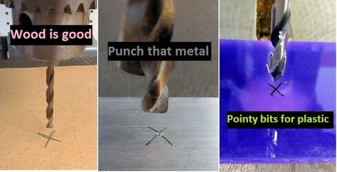
I work with 3 basic materials--wood, metal, and plastic--and each has some differences.


Drilling Holes in Wood


Wood.jpg

Wood is the easiest to work with. It is relatively soft and does what its told. Your standard drill bits will do the job.

Occasionally, your exit holes can be a little messy (particularly with MDF--the surface tears like paper). If I need a clean exit hole (that is not amenable to finish sanding) I will place a sacrificial piece of junk MDF underneath the piece I am drilling thru.
 
Last edited:
Drilling Holes in Metal

Punch%2Bthat%2Bmetal.jpg


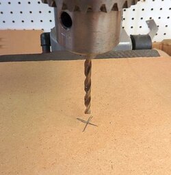
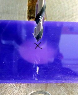
Metal is obviously much harder than wood, and has a very smooth hard surface. Drilling into a smooth hard surface causes problems because often times the drill bit will “walk” from where you want to drill your hole causing your hole to be misplaced, or creating scratches.


Walking%2Bbit.jpg


Whenever I drill metal a metal surface, I first use a center punch to create a pilot divot. The pilot divot will then catch the drill bit tip.

Simple center punch tools are essentially an augur that you tap with a hammer to create a center punch.

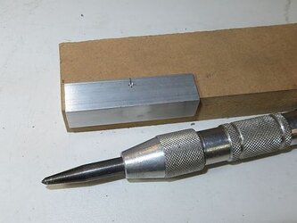
I use a spring loaded center punch like this one.


Center%2Bpunch2.jpg
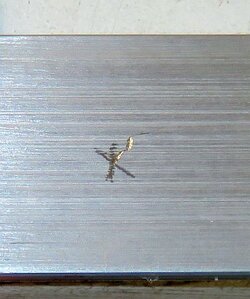
I marked my hole location with a little cross--then center-punched it. See the little divot.


The most common metal I work with is aluminum--which is pretty soft as far as metals go. Once you catch your center-punched divot, drilling the rest of the way thru the material is rarely a problem.

Steel and copper are much harder materials, so drill with patience. Sometimes you may need to let your drill bit and material cool. I will often lubricate with cutting oil or sewing machine oil.
 
Last edited:
Drilling Holes in Plastic

Pointy%2Bbits%2Bfor%2Bplastic.jpg


Plastic is a soft material with a hard and smooth surface.

2 very important phenomenon happen when drilling thru plastic:

1) Because the surface is hard and smooth, regular drill bits will often walk causing really bad scratches. However, obviously, you can’t use a center punch. You can use standard drill bits, just be very cognizant of this fact, and maybe even practice on getting the right amount of pressure to dig the drill bit into the plastic hard enough to prevent walking but not so hard as to crack it.

2) “Pull thru”--when a standard drill bit exits the far side of the plastic, it will catch on the exit surface and yank the plastic material upwards very abruptly. If you are driling near an edge, this may happen with enough force that it will actually crack the plastic to the edge. The thinner and cheaper the plastic, the nearer an edge, and the larger the drill bit, the more likely this will occur. So if you drill near an edge, clamp things liberally, or even place a sacrificial piece of wood or plastic to make a clamp sandwich.


Plastic%2Bpull%2Bthru.jpg
Pull thru caused this hole to chip out


Pull%2Bthru%2Bclamp.jpg


For plastic, by far the best solution is to purchase a few plastic-specific drill bits.

Plastic%2Bdrill%2Bbit.jpg


They go right thru plastic like butter.
 
Last edited:
Summary for Drilling Holes in Different Materials


Material%2Bdrilled.jpg
 
Last edited:
Drilling bigger holes

Drilling holes in the range of ½” and larger gets problematic.

You can start with a smaller bit and incrementally expand the hole. The problem with this is that if you step up too quickly, you’ll get a tear-out where material at the edge of the hole will just tear or shatter. This compounded by the fact that in a standard US drill bit set, the larger drill bits get disproportionately larger!

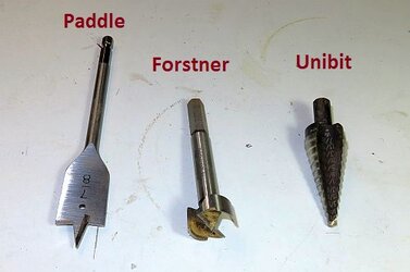
If you are working with wood, then it’s no problem, because you can switch to drill bits that cut your edge simultaneously such as a paddle bit or a forstner bit, which are not very expensive.


Larger%2Bbits%2Blabeld.jpg


If you are working with a soft metal (aluminum) or plastic, you can also use a unibit. A unibit has small increments built right into it. When using a unibit, once again use patience--keep your bits and material cool. Also, if your material is thicker than the depth of the step-up on the unibit, then you may need to drill from both sides of the material. If your material thicker than 2x the step-up on the unibit, then you may need to leave some material in the middle of the hole and finish your hole with a dremel tool and a sanding drum.


Largest%2Bbits%2Blabeled.jpg


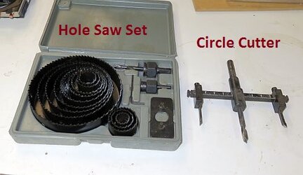
For drilling really big holes in wood, plastic, or soft metal you can use a hole saw or a circle cutter.


For drilling large holes in a hard metal--this goes beyond my expertise--I will usually visit a local metal machining shop. This may require a mill or a CNC.
 
Last edited:
Side Note on Screws


Machine Screws


6.32%2Band%2BM3.jpg


6-32 Machine Screw

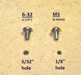
My main screw of choice is a 6-32 machine screw. The “6” refers to a number 6 sized bolt and the “32” refers to 32 turns per inch, which is the threading.

A 6-32 machine screw is just a good size overall for computer components and modding. In terms of computer parts, as far as I know, the only standard use for a 6-32 screw are the side mounts of a 3.5” hard drive and the mounts for a power supply. And a lot of companies use 6-32 thumbscrews.

An appropriate sized drill bit to create a hole to fit a 6-32 screw would be the 5/32” sized drill bit (hence in the instructions above, I mention to drill a 5/32” hole as my motherboard standoffs will be based on 6-32 screw).


M3 (Metric 3) machine screw

Since most of our components are made/designed in Taiwan/Asia, most components are based on metric screws. All of your standard hard drive, 5.25 bay devices, standard motherboard mounts, are all M3.

M3 is an excellent all purpose sized screw for computer components. If M3 were as widely available as 6-32 in the US, I’d probably mostly just use M3.

⅛” drill bit creates an appropriate sized hole for M3 machine screws.


In terms of materials for machine screws, I use zinc coated, stainless steel, or black-oxide finished screws (something that won’t react with other metals like aluminum).
 
Last edited:
Wood screws


Wood%2Bvs%2Bmachine%2Bscrew.jpg

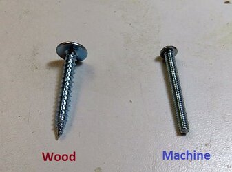
Machine screw threading (such as 32 turns per inch) create a very fine thread, meant for metals and plastic.
Wood needs a much coarser and larger thread to maintain its integrity--compare a #6 wood screw to a 6-32 machine screw.


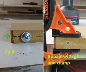
Any time you drill into wood, you generally want to drill a pilot hole. Otherwise you run the risk of splitting the wood.


Here’s an example of a classic split. With wood, a split can often easily be repaired with glue and a clamp.
Wood%2Bsplit%2Bduo.jpg
 
Last edited:
Creating Threaded Holes


Here are the steps to create a hole threaded to receive a 6-32 machine screw.


Step 1 Drill a pilot hole with a No. 36 drill bit

Threaded%2Bhole%2B1%2Bsmaller.jpg


In this case I’m creating my threaded hole in a piece of ⅛” clear acrylic.

Threaded%2Bhole%2B2.jpg


Step 2 Cut the threads with a 6-32 tapping bit in a tap tool.

Tapping bits.--Be sure to buy a quality tapping bit (I use this one). If you break off a tap whilst tapping, that is essentially an unrecoverable mistake.


Tapping tool--can be found at any hardware store--I do so much tapping, I’ve sprung for a deluxe model.

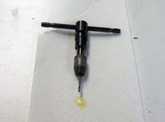
Tap%2Band%2Bcutting%2Boil.jpg


The first few turns of the tap are very important, so make sure the tap is exactly perpendicular to the hole when you start. Use patience. I often use cutting oil (that’s the glob of stuff in the picture above). I often back the tap out and clear away chips, altho in quality ⅛” - ¼” acrylic you can just power thru.


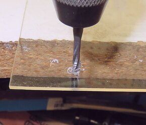
Threaded%2Bhole%2B3.jpg


Tapping thru ⅛” acrylic, I’ve done so often I know it takes 13 half turns to get thru, then slowly back the tap bit out and now you’ve got a threaded hole:
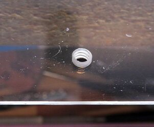
Threaded%2Bhole%2B4.jpg


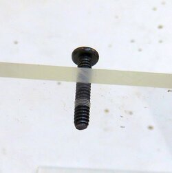
Accepting a 6-32 screw.

Threaded%2Bhole%2Bdone.jpg


To create a M3 threaded hole, use a 2.5mm drill bit with your M3 tap.

Tapping aluminum and plastic are easy.

Tapping harder metals such as copper and steel--more patience, back out often, and lots of lube. If you feel the tap straining, stop--breaking off a tap is bad bad bad. In the past, when tapping a copper heatsink, sometimes I only advance 2 half turns at a time, before backing out, clearing chips, and re-lubing.
 
Last edited:
Tapping wood

You can 6-32 machine tap wood/MDF. However, if you drive a screw in to aggressively, you could probably break away all the threading. This is not the end of the world as it merely leaves you with a larger hole. You could re-thread the hole for 8-32 or swap to wood screws.

Even if you are careful, a 6-32 tapped hole in MDF will probably wear down with time if you frequently stress the threads.


Brass Threaded Inserts

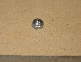
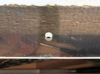
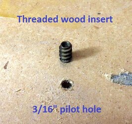
So to create a metal threaded hole in wood, I use a threaded insert. The outside has wood threading and the inside has brass 6-32 threaded interior.


Threaded%2Bwood%2Binsert1.jpg

First, drill a 3/16” pilot to accept the external wood threading.


I usually add a dab of wood glue to the outside threading and drive the metal insert into the wood hole.


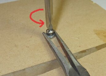
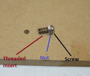
You will need a “tool” to drive the threaded insert in--you may be tempted to just use a screw--but after driving the insert in, you will find that the insert will stick to the screw and not stay in the hole. So my simple driving tool is a screw with a nut.


Threaded%2Binsert%2Btool.jpg


Using the screw head, drive the threaded insert into the pilot hole.

Threaded%2Btool%2Bdriven.jpg


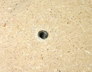
Then brace the nut and back the screw out, leaving the threaded insert behind.

Threaded%2Binsert%2Btool2.jpg


Threaded%2Binsert%2Bsuccess.jpg


It’s little hard to capture this in all still, so I made a quick video:

--> Click for Youtube video <--
 
Last edited:
Side Note on Holes and Screws = Done!!!


Main Structure: Panels

Step #4
Mount Your Motherboard


Yes, that was a big long side chapter of posts that can be mostly summarized as:

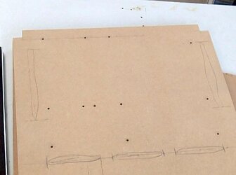
Drill a bunch of holes for your motherboard mounts:


Motherboard%2Bholes.jpg


And it may seem over-detailed, but I will take a moment to actually be specific on how I mount my motherboard:

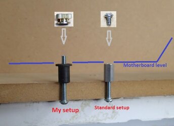
After a lot of experimentation, I came up with a method of mounting which is not the standard.

Standoffs2.jpg

A standard setup typically involves a hex threaded spacer. You put the motherboard on top of it. Then you screw it down.

For me, I need the motherboard mounted, but I rarely need it completely locked down--it’s already just laying flat. So I use a thru-screw with a ¼” portion sticking up. I can just drop the motherboard in place and it’s held pretty well. If want it completely locked in place, I can screw on a few knurl nuts. Also, importantly, no need for a screwdriver.

Here are the parts I use: 1-¼ inch 6-32 machine screw, 1/2” tall rubber well nut (aka rivet nut), and 6-32 knurl nut.


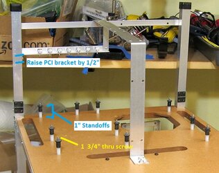
A very common mod that folks request are taller standoffs, which is no problem. Add a spacer, increase the thru-screw accordingly, and don’t forget to increase the height of the PCI bracket.

Here is picture of Station #22, where 1” standoffs were requested.


Station22%2Bmotherboard%2Bstandoffs.jpg
 
Last edited:
Main Structure: Panels


Step #5
Make your panel cutouts


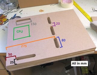
My general plan for panel cutouts consist of slots ⅞” in width, on each of the 3 sides of the motherboard. ⅞” allows for all your cables from the power supply, hard drives, optical drives, and/or watercooling tubing, which I typically locate on the lower tier.

It’s important to not make the slots so long as to compromise the strength of the panel.

I also like to include a cutout below the cpu socket for access to the backside of the motherboard.


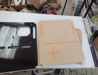
Cutout%2Bplanning%2Blabeled2.jpg


This is just my standard layout and should be modified based on needs (ie extra long or tall motherboards, etc).


As an example, in my latest benching station, the client wanted an extra + shaped pass thru for his watercooling setup:


Station30%2Blayout%2B2.5.jpg


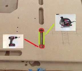
To make the slotted cutouts, probably the most common method would be:

1) Create round end holes with a drill (use a unibit, paddle bit, or forstner bit)

2) Connect the edges of the holes with a jigsaw


Cutouts%2Bdrill%2Band%2Bjigsaw%2Blabeled.jpg
 
Last edited:
Back