-
Welcome to Overclockers Forums! Join us to reply in threads, receive reduced ads, and to customize your site experience!
You are using an out of date browser. It may not display this or other websites correctly.
You should upgrade or use an alternative browser.
You should upgrade or use an alternative browser.
[Build Log] Virtual Cosmos - Cosmos II VR PC
- Thread starter Elusid
- Start date
- Thread Starter
- #22
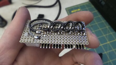
Getting started with the power injection board. It'll pass RPM and PWM directly through from left to right and inject power into the right side only from the Molex.

RPM first

PWM next

Another angle

Power

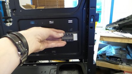
I'm thinking this is where I'll place it.

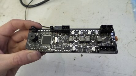
I desoldered the ugly white headers on the AQ6

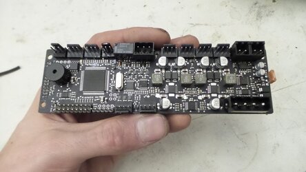
I soldered back on black ones in their place. It looks so much better!

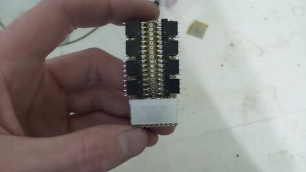
RPM first
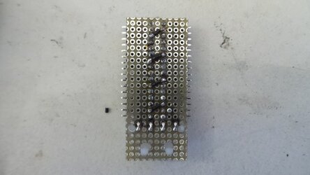
PWM next
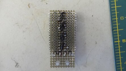
Another angle
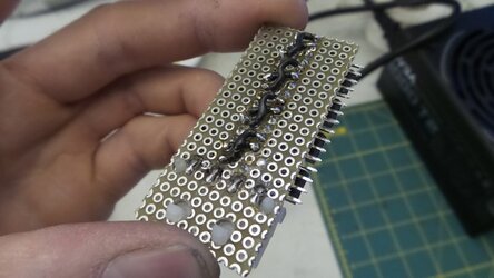
Power
I'm thinking this is where I'll place it.
I desoldered the ugly white headers on the AQ6
I soldered back on black ones in their place. It looks so much better!
Last edited:
- Thread Starter
- #23
Finished all the electrical boards for the fans. Once I confirm it all works, I'll order custom black etched PCBs  This way I can at least get all the cables cut to the right lengths, sleeved and move on.

I ordered a sample pack of MDPC-X sleeving. I'm not a fan of the material but at least it let me figure out my color scheme. I'm a huge fan of heat treated fiberglass which I've used in the past. I'm on the search for a company that will color match for me.

Waiting on the connectors and then I'll be able to crimp those fans and test the whole fan system! More to come.
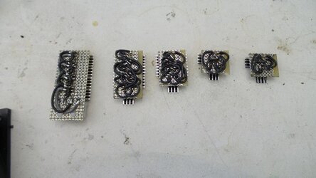
I ordered a sample pack of MDPC-X sleeving. I'm not a fan of the material but at least it let me figure out my color scheme. I'm a huge fan of heat treated fiberglass which I've used in the past. I'm on the search for a company that will color match for me.
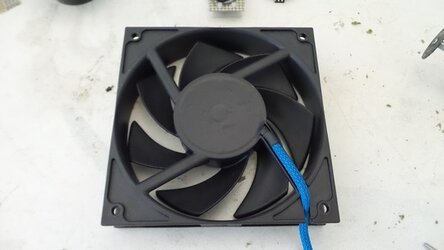
Waiting on the connectors and then I'll be able to crimp those fans and test the whole fan system! More to come.
- Thread Starter
- #24
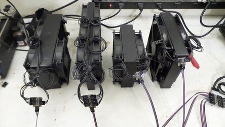
Finally got the crimp housings in the mail. First thing I had to do was crimp everything and make sure it worked like I had intended. You can see the four channels from the AQ6 go into the power injection board here and then the four ribbon cables going off to the radiators. Technically, I only needed the RPM and PWM cables from the AQ6 to the power injector, but I did all 4 for aesthetics.

Really, this radiator is the only reason I even needed to do power injection, but I went ahead and did it for all the channels. I like how it looks.

One of the 120mm fans ceased, but other than that, it looks good!

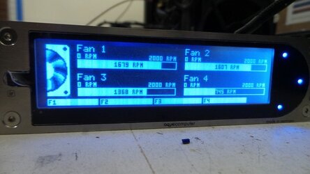
It works! I need to adjust the fan's RPM values, but it's doing everything it's supposed to. All fans set to 70% here.

Parts in the mail. More to come!
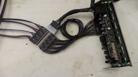
Really, this radiator is the only reason I even needed to do power injection, but I went ahead and did it for all the channels. I like how it looks.
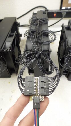
One of the 120mm fans ceased, but other than that, it looks good!
It works! I need to adjust the fan's RPM values, but it's doing everything it's supposed to. All fans set to 70% here.
Parts in the mail. More to come!
- Joined
- May 15, 2010
- Location
- Euroland, Denmark
Looks nice. Man did i have a crappy time working out how to use the AQ6 with PWM signal for fan hubs. Having to build ind the resisters on every plug just got annoying, i hope you have that sorted from the get go?
- Joined
- May 15, 2010
- Location
- Euroland, Denmark
I needed it for all my PWM stuff to work on my AQ6, before it, they refused to adjust anywhere, and being theres a 600page thread on it on another forum, i fairly sure im not a one off case, but im happy you dont need it for it to work 
- Thread Starter
- #28
Yeah, thanks. No problems I've seen so far. Dropping past 50% doesn't change the speed but I figure it's limiting itself so it won't stall. Would you mind sharing that link just in case that changes? Sounds like I should read into that.
- Joined
- May 22, 2011
- Location
- USA
You only need a resistor (Diva Mod) for a older gen. non-intel spec'd D5 PWM pump. EK now makes the gen. 2 that will work with the AQ 6. If you're referring to PWM fans , that's all news to me.
- Thread Starter
- #30
You only need a resistor (Diva Mod) for a older gen. non-intel spec'd D5 PWM pump. EK now makes the gen. 2 that will work with the AQ 6. If you're referring to PWM fans , that's all news to me.
Thanks for clearing that up. I'm going to say it's fine for now and will address it if it ever becomes a problem. I'm going with two of the Aquacoputer D5's so that won't be an issue.
- Joined
- May 22, 2011
- Location
- USA
Thanks for clearing that up. I'm going to say it's fine for now and will address it if it ever becomes a problem. I'm going with two of the Aquacoputer D5's so that won't be an issue.

Try and go with the USB/Aquabus version pump because that will leave your PWM channels alone. You could just daisy chain whatever aquabus device you want to the Aquabus high header on the AQ6 as the Aquabus low is useless now after a firmware update. Just make sure to change the aquabus ID on each of the same devices via USB first before going to a aquabus connection since the same devices, say two pumps will come with the same ID as default. I probably saved you lots of time and research there.
- Thread Starter
- #32

Try and go with the USB/Aquabus version pump because that will leave your PWM channels alone. You could just daisy chain whatever aquabus device you want to the Aquabus high header on the AQ6 as the Aquabus low is useless now after a firmware update. Just make sure to change the aquabus ID on each of the same devices via USB first before going to a aquabus connection since the same devices, say two pumps will come with the same ID as default. I probably saved you lots of time and research there.
Yeah, those are the ones I got. Should be here any day. I was wondering about the aquabus. I'm glad you can chain them together. I thought you could only do one so was planing on hooking it all up with internal USB. I may reassess. I'll mess around with it when the parts come in. Just got the USB crimp housings today.
- Joined
- May 15, 2010
- Location
- Euroland, Denmark
You only need a resistor (Diva Mod) for a older gen. non-intel spec'd D5 PWM pump. EK now makes the gen. 2 that will work with the AQ 6. If you're referring to PWM fans , that's all news to me.
I had to do it for both my Phantek PWM fan hubs. The refused to go below a certain speed before doing the "diva mod". I got 3 PWM running off my AQ6, and all 3 needed the mod to work. Granted, one is a dual D5 pump setup yes, so thats a no brainer, but the Fans, oh man did i go nuts having to figure out why that stayed are such high RPM.
- Thread Starter
- #34
I had to do it for both my Phantek PWM fan hubs. The refused to go below a certain speed before doing the "diva mod". I got 3 PWM running off my AQ6, and all 3 needed the mod to work. Granted, one is a dual D5 pump setup yes, so thats a no brainer, but the Fans, oh man did i go nuts having to figure out why that stayed are such high RPM.
Wouldn't the resistor limit the max speed? What value resistor did you use? I have a bunch here. It wouldn't be too difficult to throw a few on to test. I'm ok with my fan's slowest speed right now, but if I can increase the range without cropping off the highest speed, I'll do it.
- Joined
- May 15, 2010
- Location
- Euroland, Denmark
Wouldn't the resistor limit the max speed? What value resistor did you use? I have a bunch here. It wouldn't be too difficult to throw a few on to test. I'm ok with my fan's slowest speed right now, but if I can increase the range without cropping off the highest speed, I'll do it.
I have to be honest, i cannot remember, i bought what i got told to buy, and soldered it like i was told.
More info here: http://www.overclock.net/t/1474470/ocn-aquaero-owners-club/50
- Thread Starter
- #36
I have to be honest, i cannot remember, i bought what i got told to buy, and soldered it like i was told.
More info here: http://www.overclock.net/t/1474470/ocn-aquaero-owners-club/50
So I'm not having the problem some people seem to be having with fans. I guess there's multiple PWM specs? I just searched and skimmed honestly, but people were saying the fan speed would be low up to around 96% and then jump up to high, without any sort of linear increase. My fans range from 50%-100% just fine so I'm not worried. I'll probably keep the 120mm around 70-80%. Seems to be a good noise to air ratio.
- Thread Starter
- #37
I guess the next thing I'll work is lighting. Since I don't know how long this project will take, I'm finishing everything I know won't upgrade out from under me. I'm making an illuminated mid-plate as well as a lower bottom plate. That's the plan anyway. We'll see how it goes. Drilled the holes I could but found I had to completely remove the mid-plate to get accurate measurements.


Test fitting the angle track. I went to Home Depot and got some rivets for now. I'll order black for the final assembly.

Fits nicely.

I have a bunch of these aluminum strips from another project. They were CNC cut down to 1cm to perfectly match the width of LED strips so they'll work great for this.

Cut it down to length.

And now we have a stiff LED strip. Much easier to mount.

Perfect!

Now to finish the rest. The smaller one is for the recessed area under the PSU. I'll be doing more lighting but I ran out of LED tape. That's just what I had laying around.

I wired on 6' leads. I still have no idea how I'll be doing cable routing. My scrap cable bog is going to be overflowing when I'm done haha.

They're RGB strips but you get the point. Now to order some acrylic

I'll just store these somewhere for now.


Test fitting the angle track. I went to Home Depot and got some rivets for now. I'll order black for the final assembly.

Fits nicely.

I have a bunch of these aluminum strips from another project. They were CNC cut down to 1cm to perfectly match the width of LED strips so they'll work great for this.

Cut it down to length.

And now we have a stiff LED strip. Much easier to mount.

Perfect!

Now to finish the rest. The smaller one is for the recessed area under the PSU. I'll be doing more lighting but I ran out of LED tape. That's just what I had laying around.

I wired on 6' leads. I still have no idea how I'll be doing cable routing. My scrap cable bog is going to be overflowing when I'm done haha.

They're RGB strips but you get the point. Now to order some acrylic

I'll just store these somewhere for now.

- Thread Starter
- #38
Next wave of parts came in!

Close up of the pump assembly.

I'm using 11 temperature sensors. One for the inlet and outlet of each radiator and pump assembly, and one off the reservoir to detect case ambient. Overkill, but it was relatively inexpensive to add and I'm curious of the efficiency of each radiator and the heat dump (if any) from the pumps.

There are two things I don't like about the Fabwerk modules. The first being the white headers and the second being those horrible LED tape connectors. Trying to make a connector for them is a pain.

I swapped black headers in and male pins for the LEDs. Now I can actually crimp a cable to fit it.

Getting test loop set up.

It took a while to get this thing primed but I finally got circulation.

And here's it all running minus the flow sensor and LEDs. I need different crimps. This is all running off USB as well. I'm in the process of making a 4 pin chain for the Aquabus. I want to be able to control this whole system without a computer.

Here’s a nice screenshot of almost everything


Close up of the pump assembly.

I'm using 11 temperature sensors. One for the inlet and outlet of each radiator and pump assembly, and one off the reservoir to detect case ambient. Overkill, but it was relatively inexpensive to add and I'm curious of the efficiency of each radiator and the heat dump (if any) from the pumps.

There are two things I don't like about the Fabwerk modules. The first being the white headers and the second being those horrible LED tape connectors. Trying to make a connector for them is a pain.

I swapped black headers in and male pins for the LEDs. Now I can actually crimp a cable to fit it.

Getting test loop set up.

It took a while to get this thing primed but I finally got circulation.

And here's it all running minus the flow sensor and LEDs. I need different crimps. This is all running off USB as well. I'm in the process of making a 4 pin chain for the Aquabus. I want to be able to control this whole system without a computer.

Here’s a nice screenshot of almost everything

Last edited:
- Joined
- May 22, 2011
- Location
- USA
I can't open up the images. I wanna seeeee. lol
- Thread Starter
- #40
I can't open up the images. I wanna seeeee. lol
Oops. I was trying to post as I was running out the door. Better?
Similar threads
- Replies
- 8
- Views
- 878
- Replies
- 6
- Views
- 3K
- Replies
- 108
- Views
- 6K
- Replies
- 4
- Views
- 1K
- Replies
- 5
- Views
- 1K