• Welcome to Overclockers Forums! Join us to reply in threads, receive reduced ads, and to customize your site experience!

PROJECT LOG BatManned's Computer Build Log

Overclockers is supported by our readers. When you click a link to make a purchase, we may earn a commission. Learn More.

BatManned

Registered
Joined
Jul 15, 2016
Hello everyone! I am in the midst of custom building a gaming computer and thought I'd share my progress with this lovely forum. This build is still a work in progress but I aim to have it done by August 4th for the QuakeCon event in Dallas. So let's get the good stuff started!!

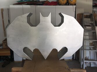
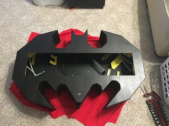
The 'End Goal' for this build is a wall mounted 'Batman' shaped gaming computer/case that will glow yellow and look AWESOME above my desk for when I play games. Did I mention AWESOME!?

Equipment:
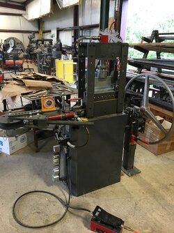
• Plasma Cam
• Press Break
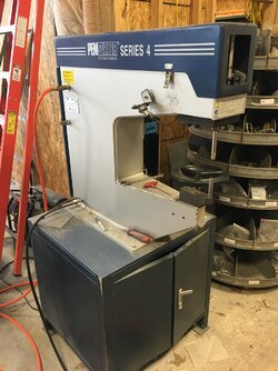
• PemSerter
• TIG Welder
• Drill / Drill Bits
• Small Angle Grinder
• Electric Sander
○ 120 and 220 Grit Sand Paper (roughly 20 sheets is what I used)
• Die Grinder
○ 40, 60, 80 Grit Sanding Tips (roughly 10 sheets is what I used)
• 1/8" Aluminum Sheets
• Rust-Oleum Truck Bed Coating Black Spray Paint (with and without built in primer)
• Foam
• Exacto Knife
• Ruler
• Protractor
• Sponge Brushes
• Paint Brushes
• 6/32" Sheet Metal Counter Sunk Scres / Nuts
~~possibly more to come~~

Software:
• AutoCAD
• Adobe Illustrator

Computer Components:
Lian-Li Motherboard Tray - Black
Phanteks PH-F140HP - 140mm Fan (6 for this build)
140mm Black Anodized Aluminum PC Fan Grill (6 for this build)
ModMyToys Anodized Illuminated 22mm Momentary Switch - Power Symbol Black / White
HDMI to DVI Cables
Pactech 4 Pin Molex Connector
Right Angle DVI Adapters
• Nvidia 960 Graphics Card
~~possibly more to come~~

Table of Contents
Phase 12 - Additional Details​
Phase 13 - New Computer Components​
Phase 14 - Finalization​
~~possibly more to come~~


Thank you for checking out my build and coming along for the journey. If you're coming to QuakeCon, come and check out the final version in the BYOC area. For those not coming to QuakeCon, I'll post images of the event and my computer being there!
 
Last edited:

Phase 1 - Planning and Sketching

Cut PC Case Octogon Grated Backing PS 2.jpg
Original Layout 2.jpg

I had the idea for this for multiple years without any idea how to actually implement it. Then I met someone who had all the tools I could possibly need and with his allowing me to use them, I got started.

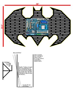
My original idea, was the back of the shape was going to be 'grated' so that I could have yellow LED lights on the inside and the lights would shine out making it have a glow effect when hanging on my wall. The grates would also be an easy way for me to just lower it onto some anchors on the wall for easy hanging.

Either way, now that I had a game plan, I used Adobe Illustrator and created what I needed in vector form so that I could scale the design to fit the size of the computer components. The bottom picture of the link shows the original grated design with size specs and an image of the motherboard to prove it would fit. I then got a motherboard tray from Lian-Li which made those dimensions too small forcing me to scale it up to a few inches. That being said, after my initial prototype, I scratched that idea and just went with a solid shaped build instead.
 

Attachments

  • Cut PC Case Octogon Grated Backing PS.jpg
    Cut PC Case Octogon Grated Backing PS.jpg
    1,014.7 KB · Views: 303
Phase 2 - Initial Set-Up

IMG_0196 2.jpg
IMG_0197 2.jpg
IMG_0198 2.jpg
IMG_0199 2.jpg
IMG_0200 2.jpg
IMG_0201 2.jpg
IMG_0202 2.jpg
IMG_0203 2.jpg
IMG_0204 2.jpg
IMG_0206 2.jpg
IMG_0207 2.jpg
IMG_0208 2.jpg

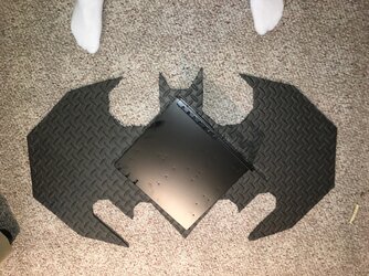
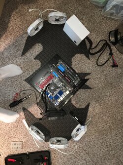
Initially, using foam that I found at Wal-Mart that was designed for flooring underneath weight training equipment, I used an Exacto Knife to cut out the main shape of the design. Using a ruler to determine the sizing of each section, and a protractor to determine the angles, I started cutting out the bat symbol.

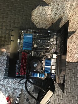
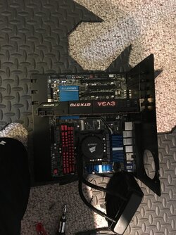
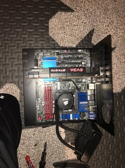
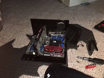
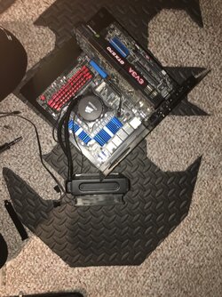
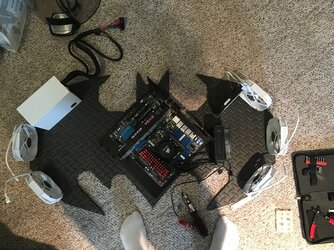
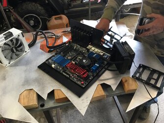
Once complete, I had to make sure the motherboard tray would fit properly within the layout. That being the single largest internal item, it was my biggest concern. As you can tell from the pictures, in this stage, I was cutting that a bit close and ended up enlarging it slightly later on. After that, I took apart my current computer and placed the pieces in locations within the shape that I thought would fit and flow well inside. I plan to have all the fans on the right hand side, including the heat-sink's cooling fan/radiator blowing in and to the left hand side; while at the same time, the left side fans will be pulling the air from the right and blowing it outside. This will hopefully keep things inside from getting excessively hot.

Now that I am happy with the layout, I intend to move to phase 3 for cutting it out and getting it physically shaped.
 
Phase 3 - Cutting/Bending/Setting
- Pics
- Video
- Video
- Video
- Video
https://vimeo.com/174151649 - Video
https://vimeo.com/174151660 - Video​

IMG_0291 2.jpg
IMG_0292 2.jpg
IMG_0293 2.jpg
IMG_0294 2.jpg
IMG_0295 2.jpg
IMG_0296 2.jpg
IMG_0308 2.jpg
IMG_0429 2.jpg
IMG_0430 2.jpg
IMG_0431 2.jpg
IMG_0435 2.jpg
IMG_0436 2.jpg
IMG_0437 2.jpg
IMG_0439 2.jpg
IMG_0440 2.jpg
IMG_0441 2.jpg
IMG_0442 2.jpg
IMG_0443 2.jpg
IMG_0444 2.jpg
IMG_0297 2.jpg
IMG_0298 2.jpg


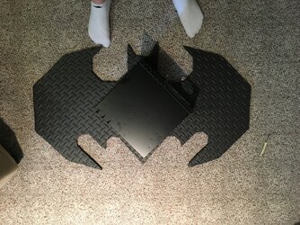
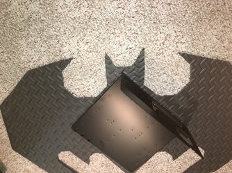
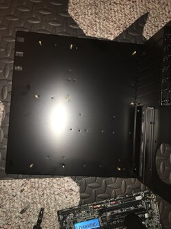
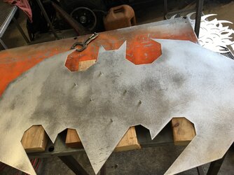
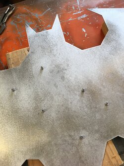
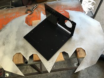
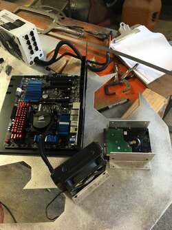
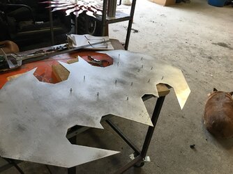
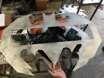
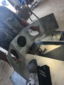
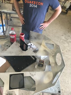
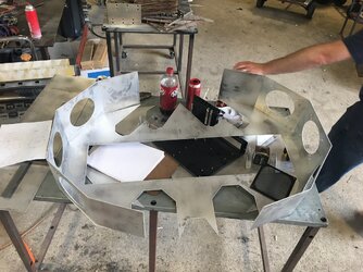
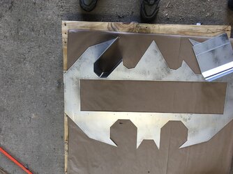
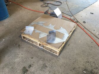
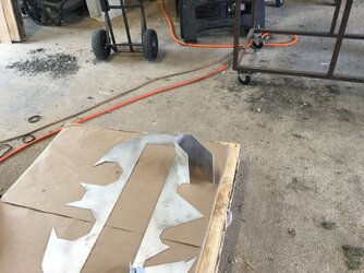
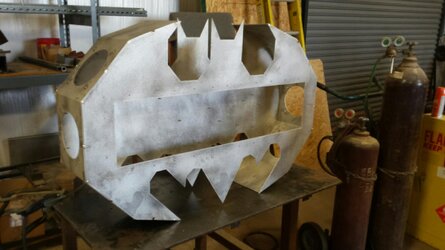
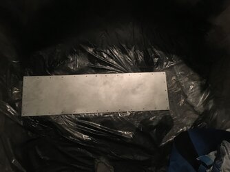
At this point, since I'm not all that proficient at using Auto Cad, I sent the Adobe Illustrator Design to a coworker who used it for his Auto Cad software and we started cutting out the necessary shapes. The first image is the image left on the counter after sanding the barbs off the aluminum that was just cut. After cutting the front panel, I placed the motherboard tray in the middle again to make sure it still fit. Then using some of the holes that my motherboard itself doesn't use, we inserted screws to allow me to bolt down the motherboard tray. By the way, the piece that all the computer parts are being attached to in the beginning images, will be the inside of the front panel.

Then, again, we set out all of the computer components to make sure we knew exactly where we wanted to place everything. We cut and bent elbow pieces that we could bolt the hard drive and coolant fan to; measuring where they would be placed so we could once again insert screws to attach it to the base. Then we did the same thing for the Power Supply.

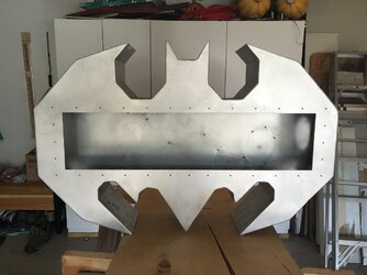
Since all was going well, we cut out the next portion of the case, the back. This time, I needed to make sure to have an access panel; obviously so I can access the computer components for future changes and/or upgrades.

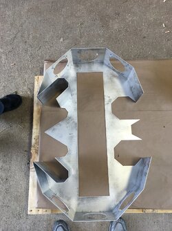
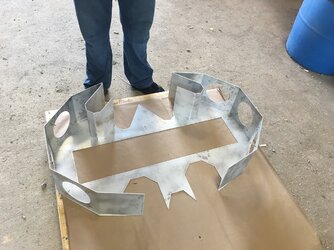
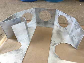
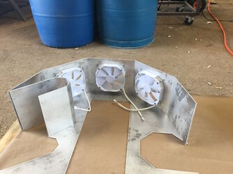
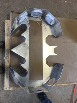
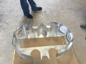
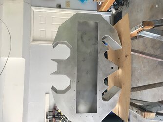
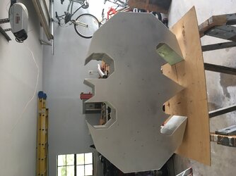
From here, is when it actually starts getting 'harder'. We decided the depth of the case would be good at 7.5", but for extra cushion, we made it 8". Using a ruler to measure out the fans and the grill hole locations, we drew it up using AutoCAD and cut it all out, bent the pieces where they needed bending, and then inserted the screw locations for the fans. After that we just measured, cut, and bent the other portions as needed. As you can see from the final images, I placed each of the depth pieces on the back shape to show how it would look in a more 3D aspect.
 
Phase 4 - Welding
IMG_0575.JPG
IMG_0621.JPG
IMG_0622 2.jpg

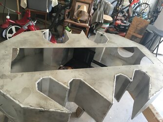
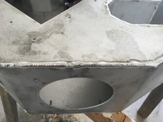
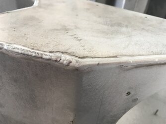
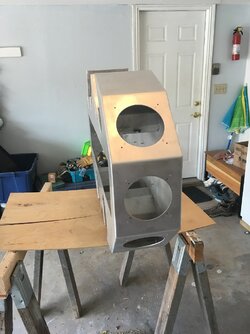
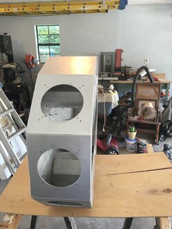
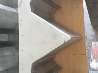
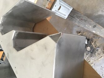
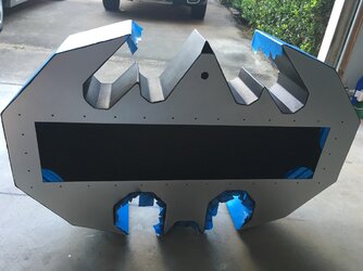
Now that we had all the pieces together and situated, we needed to weld. For concern of warping, we welded little bits at a time until the shape gained enough structure that warping was no longer a concern. The original plan at this stage was to weld about an inch or so, then leave an inch or so gap and so on until it was done. The gap was going to be filled with Bondo so that it would still look good and sealed, but after doing the little welds all around and it gained some structural integrity, I didn’t feel that warping was going to be an issue any more. So then we welded the entire thing all around instead and it looks fantastic. That being said, the welding of course left it looking very dirty and the edges were very uneven.
 
Phase 5 - Sanding
IMG_0623 2.jpg
IMG_0637 2.jpg
IMG_0638 2.jpg
IMG_0639 2.jpg
IMG_0640 2.jpg


Sanding. Sooo much sanding. I'd say I spent about 30 hours of sanding on this, the way I did it at least...

I started sanding with an electric sander using a 5" round, 120 grit sand paper on each of the flat surfaces along the edges. I sanded down the welding to make it look flush with the panel surfaces. I did that along all the flat sides as best I could. For this case, the size of my sander being so big, I couldn't fit it into the smaller wing areas to sand. Due to that, I had to use a Die-Grinder starting with 40 grit sand paper adapter to get into the small areas. Since 40 grit shaves a lot of the aluminum off at a time, once it got relatively flush, I changed to the 60 grit. Then for smoothness, I changed again to 80 grit.

Now that the edges looked flush with the panels, I went back over each of the corners to make them a more rounded and smooth finish. Once it all felt good, with no major bumps or grinds against my finger tips, I went over the entire thing with 220 grit sandpaper. At this point, since I knew I would be giving it a textured paint, I decided I didn't need to sand at a higher grade grit.
 
Phase 6 - Double Check
IMG_0663 2.jpg
IMG_0664 2.jpg
IMG_0665 2.jpg
IMG_0666 2.jpg
IMG_0667 2.jpg
IMG_0668 2.jpg
IMG_0669 2.jpg
IMG_0670 2.jpg
IMG_0671 2.jpg


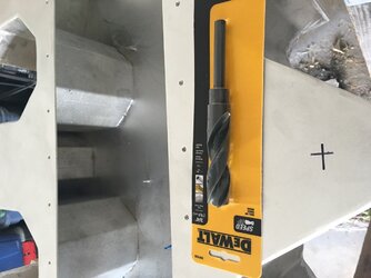
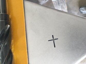
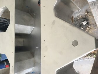
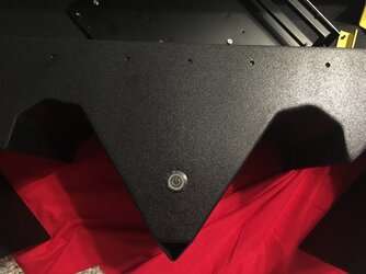
At this point I realized I didn't cut the hole out for the power button, so I used a drill with a 3/4" bit to easily cut it out. Actually, I drilled a smaller hole first so that the larger drill bit would drill in more smoothly. I then used a metal file to smooth out the hole and fit in my power button to make sure it fit properly.

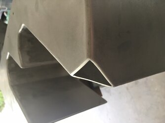
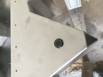
I also decided to carve out the back side of the tail to allow all the cables to come out. I measured about 3/4" down and 3/4" across the the other 2 sides forming a triangular hole. I used a Small Angle Grinder to cut through the metal giving me the hole needed for cabling. Then using the same sanding method from before I sanded down the triangular access hole making it smooth just like the rest of the case. I then verified the hole was large enough for the power cable to go through. If anyone is wondering, the power cable wasn't the largest cable as I had thought. I'll get into why this matters in a future post, which I had to fix with a little creative thinking.
 
Phase 7 - Painting
IMG_0674 2.jpg
IMG_0675 2.jpg
IMG_0676 2.jpg
IMG_0677 2.jpg
IMG_0678 2.jpg
IMG_0685 2.jpg
IMG_0686 2.jpg
IMG_0687 2.jpg
IMG_0688 2.jpg
IMG_0689 2.jpg
IMG_0690 2.jpg
IMG_0695 2.jpg
IMG_0696 2.jpg
IMG_0701 2.jpg
IMG_0702 2.jpg
IMG_0703 2.jpg
IMG_0704 2.jpg
IMG_0705 2.jpg
IMG_0706 2.jpg
IMG_0708 2.jpg
IMG_0709 2.jpg


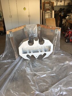
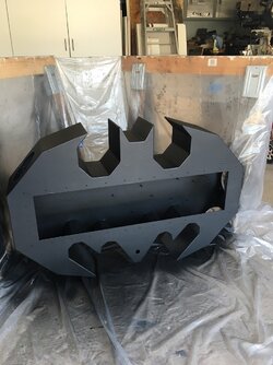
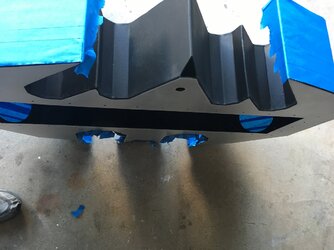
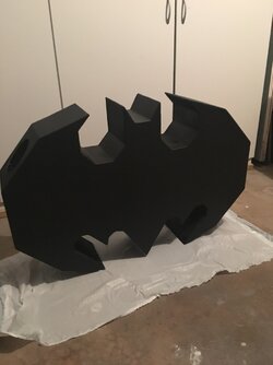
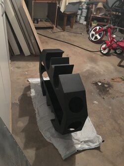
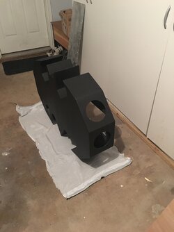
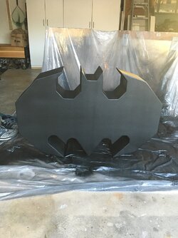
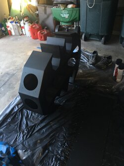
Getting super excited that it is all coming together so far, I start to paint using Rust-Oleum Truck Bed Liner Paint. Specifically, the one that has primer built into the spray can. I basically just started spray painting it as I would any other project, but ended up with some unsatisfying build up spots on the back view of the case. I decided that I would focus the first of my efforts on the depth portion of the case as it was very irregular to get the paint to spray evenly from each of the angles. You can see from some of the images there are ‘bad spots’ which I chose to ignore until I felt good about the depth. I also (somewhat) focused on the interior paint. This not being a crucial concern for perfection, but I did want it to match the outside.

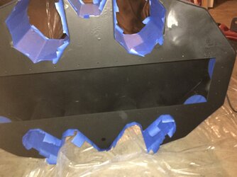
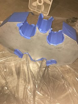
Once the depth all looked good to me, I taped it off with painters tape attempting to protect it from the debris that would occur from sanding the back panel again. This worked out okay, but in hindsight, it was probably unnecessary.
Anyway, I sanded the back plate so that it was smooth and ready for a fresh new coat. I didn’t want to mess up the depth portions though, so I re-taped this area so that I wouldn’t accidently do something to the good portion and have to redo it again, sanding and all.

This worked out perfect as I was able to give a nice even coat all around the back and front panels. After removing the tape and moving the case off the plastic I noticed there were a couple of areas I didn’t like. Either the tape pulled some of the paint off or it was just really dusty and I couldn’t wipe the dust off nicely. As a secondary coat / fixing slight errors; I used the Rust-Oleum truck bed liner paint that did NOT have the primer included. I’m not a paint expert, but it seemed that this paint went on lighter and not as thick, so I used it to do touch ups.

I also want to note that I live in Texas and the plastic I laid down to paint the case, ended up melting to the bottom wings where it touched down. I ended up taping off a large area around the melted plastic area and had to sand the paint and plastic off so that I could paint it again.

At this point, the case looked awesome and very nicely painted. There were no major flaws that stood out and I was happy with it. I then painted the back panel that covers the access opening which I apparently forgot to take pictures of… my bad.

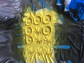
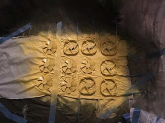
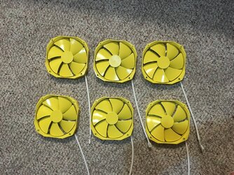
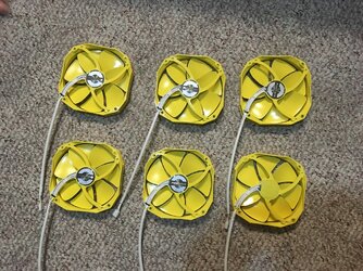
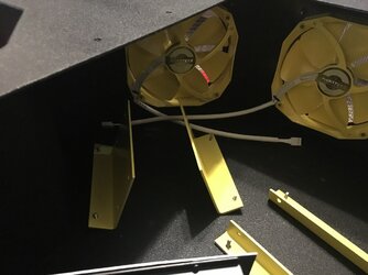
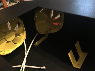
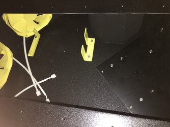
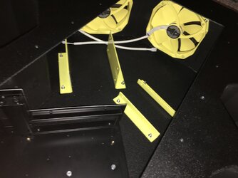
Anyway, I moved on to the fans / ‘elbow’ pieces next. Being that this case is Batman, and I grew up with batman being black and yellow colors, I wanted to give it some character making these pieces yellow. I also have the intent on adding yellow LED lights so this is just for aesthetic purposes.

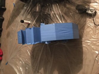
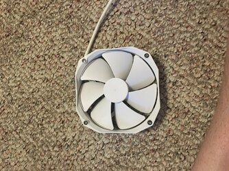
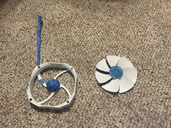
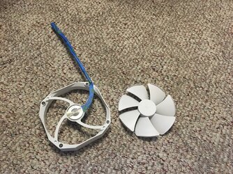
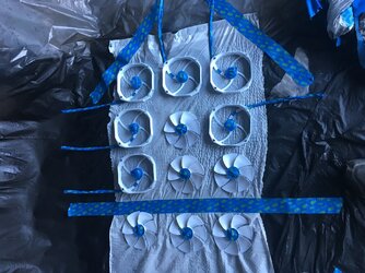
I pulled apart the fans and used painters tape to cover all the cables / open areas that paint shouldn’t go. I could have painted the cables I think, but I didn’t want to risk it and them not be usable. Overall, they came out rather well and the slight areas that are still white, doesn’t bother me.

I just realized, I didn’t take pictures of the ‘elbow’ pieces being painted. Guess you’ll just have to wait till the next post to see that those are yellow too.
 
Coming along nicely.

It's probably good that you didn't paint the cables. The paint would have probably cracked when wiring them.
 
Phase 8 – Starting to install

IMG_0710 2.jpg
IMG_0711 2.jpg
IMG_0712 2.jpg
IMG_0713 2.jpg
IMG_0714 2.jpg
IMG_0715 2.jpg
IMG_0716 2.jpg
IMG_0717 2.jpg
IMG_0718 2.jpg
IMG_0719 2.jpg
IMG_0720 2.jpg
IMG_0721 2.jpg
IMG_0722 2.jpg
IMG_0723 2.jpg
IMG_0724 2.jpg
IMG_0725 2.jpg
IMG_0729 2.jpg
IMG_0730 2.jpg


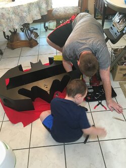
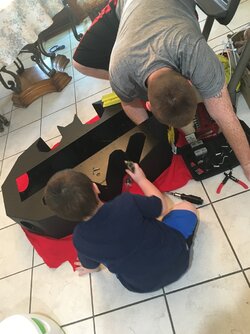
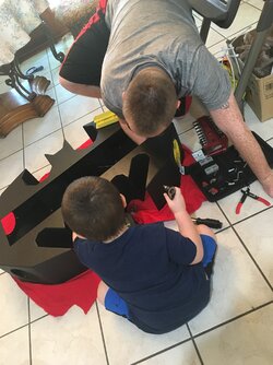
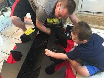
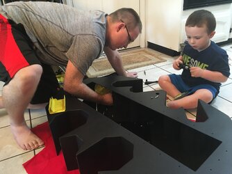
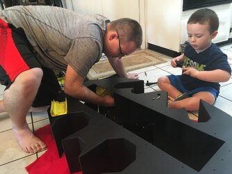
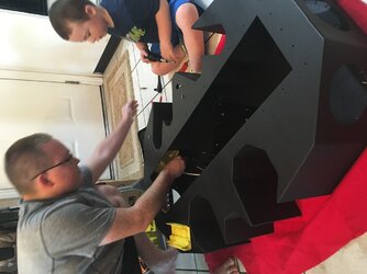
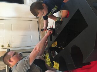
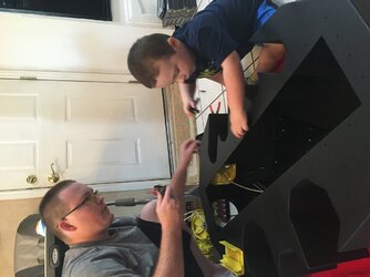
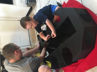
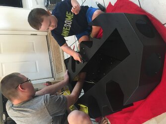
Just for extra assured purposes, I waited about a full 24 hours making sure the paint settled and dried before bringing it inside. I placed some scrap felt down on the ground to protect the floor / case from scratching. I have a two year old son who is the BIGGEST helper ever >.>

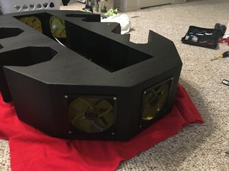
As you can see, he just had to help daddy use all the wonderful tools he could get his hands on. Anyway, I installed the fans first as the corner areas that go to the wings give little to no room for easily attaching the nuts to the screws. I expected this to be much harder but it actually wasn’t too bad.

Just for placement, I put the elbow pieces in there to verify that all the fans would fit as well as the computer components. I originally was thinking that the fan immediately next to the power supply wouldn’t fit and would just be an open area. Being hopeful, I tested to see that both would fit and it did.
 
Back