- Joined
- Sep 23, 2016
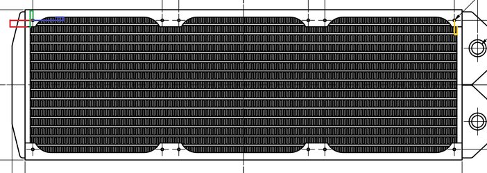
O.K finally managed to get the design docs for the Alphacool NexXxoS UT60 Full Copper 360mm Radiator and the 420 version, by the looks of it the files are there on their site but it seems to be having problems with direct download and would only work when they sent me a link.
Now I have asked Alphacool this question but have not had an answer yet so I thought I'd pose it here as I am custom building a computer case and am now down to the last part - the rads.
The documents provided by the site do provide the basic measurements but don't supply distance offset from the screw holes to the edges of the shroud - can anyone explain to me how to calculate these distances from the information provided as I am trying to determine the distances shown with colours with values calculated from the supplied PDF documents and I'm pretty much ripping my hair out at this point because I can't figure out how.
View attachment 120-360-60.pdf
View attachment 140-420-60.pdf

Last edited: