• Welcome to Overclockers Forums! Join us to reply in threads, receive reduced ads, and to customize your site experience!

How to switch between 2 power supplies?

Overclockers is supported by our readers. When you click a link to make a purchase, we may earn a commission. Learn More.

cayla

New Member
Joined
Oct 23, 2016
HNv6C.jpg
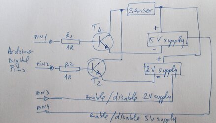
I have a sensor that needs in order to function 30 seconds 2V, 30 seconds 5V (on both max 300mA). I have done the power supplies, I can do the programming for the delay but I'm not sure exactly how to switch between them using some types of transistors. Can anyone help?

What I need is a kind of switch that on digital LOW goes on the 2V supply, and on HIGH goes to the 5V supply. What transistors should I use so they can be controlled from a digital PIN from Arduino and handle the max. 300mA current the sensor needs?


Please see the image for my idea (I'm a totally noob in electronics). Both supplies are done with MAX603/4 so they have an OFF switch. T1/T2 are 2N2222(see datasheet here) and I was thinking that I can disable one supply then enable the other one and so on. Will this work? If yes by just disabling/enabling the supplies .. maybe Pin1/Pin2 are useless. What do you think?

Thank you!
 
Could you not use a 5v power supply and use a linear or shunt regulator to control the 2v? Should simplify things.
 
I can think of two ides:

1) You could use an adjustable regulator (such as a LM317). You have 2 resistors in series on the "adjust" leg with a transistor connected to your digital signal. When the transistor is on, it shorts out one resistor...when it's off you have both in series...hence giving you the two different voltage adjust levels. You only need 1 power supply.

2) You could also use an op-amp, with the output directly shorted to the negative input. You feed in 5V into the positive input through a series resistor, and then a transistor in series with a resistor to ground. When the transistor is on, you get a voltage divider, and the output voltage of the op-amp will drop. With the transistor off, you get unity gain and 5 V out of the op-amp. You only need 1 power supply.

With approach (1), it's best to have the transistor go to ground...to avoid having to do any biasing of the gate/base.

The biggest challenge with (2) is finding an op-amp that could source 300 mA. They exist though. However, you could simply connect the output of a low power op-amp into a push/pull transistor output stage to get the current you need.

:thup:
 
Back