• Welcome to Overclockers Forums! Join us to reply in threads, receive reduced ads, and to customize your site experience!

HD 7970 mod

Overclockers is supported by our readers. When you click a link to make a purchase, we may earn a commission. Learn More.
awesome lochekey, just awesome.

AS much as I would love to claim credit for that most recent picture it belongs to another guy over at HWBOT. You can find his profile here. He does some amazing work. Mine pale sin comparison. Thanks for the vote of confidence though.
 
So I have been contemplating how to do the OCP mod and I am thinking about doing it slightly differently than what I have seen before. I am planning on building 2 bus resistors one rated at 450k ohm and one at 250k ohm. The ground pin from each of these will then be tied to a switch that is grounded. By toggling the switches I will have basically 4 different settings 450k/250k/160k/off. This should allow me to use this with various cooling methods without having the phases kill themselves. The only major problem I see with this is that there will be a constant 160k resistance between the pickup points on the card even when it is turned off. I do not know how this will effect things or if it will cause noise in the circuitry.

What does everyone think, do you see a better way of going about this? I am trying to avoid having to swap resistors out like Bobnova did, I will if I have to but wanted to avoid that extra socket if possible.
here's my help :shrug: :D
 
here's my help :shrug: :D

Here you can read this article that has been giving me a headache. It explains the principal of OCP using the vdrop across the vrm inductor to calculate amperage(I think). Maybe you can help me with the math as it all looks Egyptian to me tonight.
 
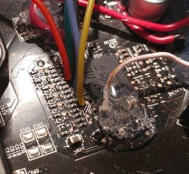
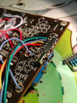
Ok well I got the wires soldered on for the OCP mod. Man was this area tight, I might have to invest in even smaller wire next time as this is 30 gauge wire and it barely fit. Even under a magnifying glass this is hard to inspect so I am going to spend some more time testing it before gluing it on and I am hiding it from my cat this time:clap:. Still need to source some resistors and figure out what I am doing there and then I should be ready to finish this up.
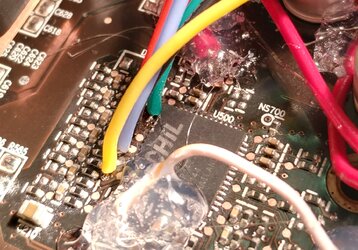
0227172117_HDR.jpg
0227172117b_HDR.jpg
 
my gawd, lochekey, if you can see all that, you must be a teenager.
props to you for persistence buddy, keep at it.
 
^ He's been rodeo clown for quite awhile now. Probably since the Peas and Carrots episode. LMAO
 
Would audio grade resistors (non conductive) help with that? If it's still a concern.

I am not familiar with these so wil have to do some research to answer this. I have been considering installing a diode inline for each phase before the resistors to help prevent crosstalk. I don't know if this is worth the hassle as I may be overthinking this.

my gawd, lochekey, if you can see all that, you must be a teenager.
props to you for persistence buddy, keep at it.

Not quite that young:D. Really though a 10x magnifying glass does wonders.

I think Lochekey has gone full Rodeo Clown! :D

Me? Never I think you are imagining things :chair:


^ He's been rodeo clown for quite awhile now. Probably since the Peas and Carrots episode. LMAO
In my defense that worked really well. I still contend that frozen tomatoes is the way to go due to their high water content.
 
Ok so I picked up some resistors and some pin sockets and built an interchangeable setup. I want to test this out and if I like it I will build a few more with different resistor values so I can easily switch this out.

0302172332.jpg
 
Got done work early today and had a chance to finish mounting everything. So I mounted the wires for the OCP mod to an empty pin socket and wired the pin socket to ground via a switch.

8668.jpeg

I then helped my stock in the hot glue company and got everything attached well and inserted the homemade bus resistor.

8670.jpeg

This has resulted in a drop of resistance on each pin from 5.75kohm to 5.73kohm. I don't know how big of a difference this will make but can swap out the resistors as necessary.

Finally a picture of my completed mods. The end of the card is getting a little busy but hey it works.

8672.jpeg
 
Supposed to be single digit tenors tonight. If I get home in time I will get it plumbed in and stick it outside to see.
Same here, hoping to get the 1800x on the benching loop. I will usually see 2c delta temps, so the loop should be around -4 to -8c. :D
 
Haven't touch any hardware since the team cup this thread got me jonesing to take a iron to something

Great work lochekey love it :clap:

Did you ever get around to benching the card if so how did it go?
 
Hey quickfast howare you doing. It is funny you ask about testing. I am sitting here tonight doing some runs.

9097.jpeg
 
Last edited:
Back