Preface: This post is in reply to the AMD RyZen CPU thread, but I figured there needed to be a separate location for this discussion. This is for more general understanding of how the VRM Power plane operates with a CPU. I'll try not to make this vendor specific.
Common Terms:
Id : Drain Current
Vgs : Gate to Source Voltage
Vds : Drain to Source Voltage
Rds : Drain to Source Resistance (usually given in mill-Ohm)
Tj : Transistor Temperature at Junction
Introduction:
Why is it that for overclocking a CPU, the crucial system the VRM power plane must be kept under constant temperature control? As is the case with all overclocking, the more we push a system the more heat is created from said system. In the case of power, this can cause huge ramifications for the CPU's consistent overclocking potential. As feature size of the the CPU transistors decrease, 14nm to 5nm, we will see more transistors packed into the same or relatively the same package size. The feature size decrease also means that less power is required, but the power that is required becomes even more crucial. The power delivered is now dispersed among more transistors, so any issue in power delivery could cause larger issues in the CPU. That isn't to say this issue was not seen in past generations, but power planes had less stringent rules, and had some error margin to operate in.
Basics:

source
The CPU VRM Plane (and just about all VRM planes on a standard x86 motherboard) utilize the buck MOSFET switching system or commonly known as a DC-DC converter. This system utilizes two FETs, an inductor and a capacitor to step a large voltage load down to a lower voltage load while increasing current. To do this, a high side FET (Q1) and a low side FET (Q2) will switch to produce a steady state current and voltage into the inductor. Once through the inductor, the capcitor will store parts of the load to maintain a constant supply of power into the CPU (LOAD). The switching of the high side FET and the low side FET is polar opposite of each other. Which means that the high side FET will be one while the low side FET will be off, and vise versa is true. This switching time is translated into Duty Cycle, the ratio difference of high side FET turned on to the low side FET turned on.
In order to keep this system in a steady state to which deliver a constant amount of current and voltage to the CPU, the Duty Cycle needs to be high while the resistance of the path of Vin to the CPU is as low as possible.
Break down:

source
Current supplied to the CPU is produced in a triangle wave. If the Duty Cycle were to increase, the peaks of the trangle waves would come closer, raising the continuous supplied current. In the graph above, the dashed line Io would increase as IL would smush together.

source
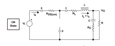
However, the path for the current to be pushed through the inductor is impeded by the resistance of the high side FET (Rds(on)) and the resistance of the inductor (RL).
The resistance of the high side FET and the inductor play a crucial roll into how well a DC DC converter can operate. This relation also plays into the reason of this post: Why current stability plays a crucial roll in maintaining consistent overclocking of a CPU. There several dozens of factors that play into creating a perfect DC DC converter, but not all of them are top priority. I will break down two areas that I see as very important for stabilizing constant current for an overclocked CPU. They are the MOSFET current output which will deal with Rds, and FET to Inductor which will go into inductor resistance (RL). Later I'll pull everything together and hopefully give a good break down for everyone to understand.
MOSFET Current Output:
FET's current output is most commonly referred to as Id or Current from the Drain pin of the FET. A FET is typically rated to output a max current dependent on the resistance between the FET's Drain to Source pins (Rds), the voltage between the Gate and Source pins (Vgs), and the voltage between the Drain and Source pins (Vds), and Temperature of the junction between the Drain and Source pins (Tj). For our x86 motherboards, Rds is constant (with respect to Tj, more later), and Vds is roughly constant. Vds is the voltage input from the 8pin CPU connector, and is so ~12V. Rds has to be calculated but it be between 0.001 to 0.004 Ohms.
In this section I will use the OnSemi NTMFS4C06N FET for examples. We can see that the Id Max is 69A when we have a 30V input and Vgs around 4.5V. This is not too useful for us since our systems uses 12V input, but about the same for Vgs and a lower current input. So for our case we should expect to see Id Max higher. We can roughly determine this by looking at the figures that OnSemi has provided in their data sheet. There are a few figures that we should be looking at, and those are Fig1, Fig2, Fig4, and Fig5. These charts will best describe what we might expect in terms of Id and Rds when temperature varies.

Let us first look at Fig1 to get an idea of what kinda of current we might expect depending on Vds and Vgs. In the case of our CPU DC-DC buck converter, we should see around ~15V for Vds but our Vgs should be between 4-5V. From Fig1 we can see that our Id will be really high, ~120A+! But Tj is equal to 25C, and this will never happen. In fact our Tj can vary between 50C to 80C or greater depending on conditions.

So let's go over to Fig2 to get an idea of what our Tj does to our Id. Here you can see that as temperature increases, Vgs needs to decrease to maintain the same operating current. However, we see that if we increase Vgs that we can stabilize our current even as Tj increases. Vds does not matter for this chart, all you need to know is that it is a constant rate.


Not until we factor in Rds do we notice that raising Vgs would do little in maintaining constant current delivery. When Temperature increases, current capacity falls, because Rds increases. Fig4 and Fig5 show the relation of Rds to Id and Tj.

http://www.taiwansemi.com/upload/files/products/Application_Note/AN-1001_A1611.pdf
So let's bring these relationships together in a mathematical form to simply understand how we produce current from the FETs. With the equation above we can now see that the total Id is dependent on the squared ratio of Temperature vs Resistance of the device. To summarize: Current will stay steady when Temperature increases but Resistance decreases during utilization. Yet from the information above, we know that Rds increases when Temperature increases. So thus, in order to maintain a steady current output we must maintain temperature as to not raise Rds.
More to come later:
FET to Inductor
Understanding the entire VRM system with its relation to Current vs Temperature
Common Terms:
Id : Drain Current
Vgs : Gate to Source Voltage
Vds : Drain to Source Voltage
Rds : Drain to Source Resistance (usually given in mill-Ohm)
Tj : Transistor Temperature at Junction
Introduction:
Why is it that for overclocking a CPU, the crucial system the VRM power plane must be kept under constant temperature control? As is the case with all overclocking, the more we push a system the more heat is created from said system. In the case of power, this can cause huge ramifications for the CPU's consistent overclocking potential. As feature size of the the CPU transistors decrease, 14nm to 5nm, we will see more transistors packed into the same or relatively the same package size. The feature size decrease also means that less power is required, but the power that is required becomes even more crucial. The power delivered is now dispersed among more transistors, so any issue in power delivery could cause larger issues in the CPU. That isn't to say this issue was not seen in past generations, but power planes had less stringent rules, and had some error margin to operate in.
Basics:

source
The CPU VRM Plane (and just about all VRM planes on a standard x86 motherboard) utilize the buck MOSFET switching system or commonly known as a DC-DC converter. This system utilizes two FETs, an inductor and a capacitor to step a large voltage load down to a lower voltage load while increasing current. To do this, a high side FET (Q1) and a low side FET (Q2) will switch to produce a steady state current and voltage into the inductor. Once through the inductor, the capcitor will store parts of the load to maintain a constant supply of power into the CPU (LOAD). The switching of the high side FET and the low side FET is polar opposite of each other. Which means that the high side FET will be one while the low side FET will be off, and vise versa is true. This switching time is translated into Duty Cycle, the ratio difference of high side FET turned on to the low side FET turned on.
In order to keep this system in a steady state to which deliver a constant amount of current and voltage to the CPU, the Duty Cycle needs to be high while the resistance of the path of Vin to the CPU is as low as possible.
Break down:

source
Current supplied to the CPU is produced in a triangle wave. If the Duty Cycle were to increase, the peaks of the trangle waves would come closer, raising the continuous supplied current. In the graph above, the dashed line Io would increase as IL would smush together.
source
However, the path for the current to be pushed through the inductor is impeded by the resistance of the high side FET (Rds(on)) and the resistance of the inductor (RL).
The resistance of the high side FET and the inductor play a crucial roll into how well a DC DC converter can operate. This relation also plays into the reason of this post: Why current stability plays a crucial roll in maintaining consistent overclocking of a CPU. There several dozens of factors that play into creating a perfect DC DC converter, but not all of them are top priority. I will break down two areas that I see as very important for stabilizing constant current for an overclocked CPU. They are the MOSFET current output which will deal with Rds, and FET to Inductor which will go into inductor resistance (RL). Later I'll pull everything together and hopefully give a good break down for everyone to understand.
MOSFET Current Output:
FET's current output is most commonly referred to as Id or Current from the Drain pin of the FET. A FET is typically rated to output a max current dependent on the resistance between the FET's Drain to Source pins (Rds), the voltage between the Gate and Source pins (Vgs), and the voltage between the Drain and Source pins (Vds), and Temperature of the junction between the Drain and Source pins (Tj). For our x86 motherboards, Rds is constant (with respect to Tj, more later), and Vds is roughly constant. Vds is the voltage input from the 8pin CPU connector, and is so ~12V. Rds has to be calculated but it be between 0.001 to 0.004 Ohms.
In this section I will use the OnSemi NTMFS4C06N FET for examples. We can see that the Id Max is 69A when we have a 30V input and Vgs around 4.5V. This is not too useful for us since our systems uses 12V input, but about the same for Vgs and a lower current input. So for our case we should expect to see Id Max higher. We can roughly determine this by looking at the figures that OnSemi has provided in their data sheet. There are a few figures that we should be looking at, and those are Fig1, Fig2, Fig4, and Fig5. These charts will best describe what we might expect in terms of Id and Rds when temperature varies.
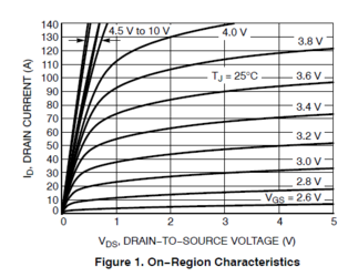
Let us first look at Fig1 to get an idea of what kinda of current we might expect depending on Vds and Vgs. In the case of our CPU DC-DC buck converter, we should see around ~15V for Vds but our Vgs should be between 4-5V. From Fig1 we can see that our Id will be really high, ~120A+! But Tj is equal to 25C, and this will never happen. In fact our Tj can vary between 50C to 80C or greater depending on conditions.
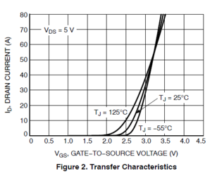
So let's go over to Fig2 to get an idea of what our Tj does to our Id. Here you can see that as temperature increases, Vgs needs to decrease to maintain the same operating current. However, we see that if we increase Vgs that we can stabilize our current even as Tj increases. Vds does not matter for this chart, all you need to know is that it is a constant rate.
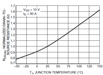
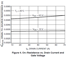
Not until we factor in Rds do we notice that raising Vgs would do little in maintaining constant current delivery. When Temperature increases, current capacity falls, because Rds increases. Fig4 and Fig5 show the relation of Rds to Id and Tj.

http://www.taiwansemi.com/upload/files/products/Application_Note/AN-1001_A1611.pdf
So let's bring these relationships together in a mathematical form to simply understand how we produce current from the FETs. With the equation above we can now see that the total Id is dependent on the squared ratio of Temperature vs Resistance of the device. To summarize: Current will stay steady when Temperature increases but Resistance decreases during utilization. Yet from the information above, we know that Rds increases when Temperature increases. So thus, in order to maintain a steady current output we must maintain temperature as to not raise Rds.
More to come later:
FET to Inductor
Understanding the entire VRM system with its relation to Current vs Temperature
Last edited: