• Welcome to Overclockers Forums! Join us to reply in threads, receive reduced ads, and to customize your site experience!

need help connecting case io front panel to new mobo

Overclockers is supported by our readers. When you click a link to make a purchase, we may earn a commission. Learn More.

kaitlin4599

Member
Joined
Jul 15, 2013
need help building my desktop. ok so i have an HP Pavilion a6334f Desktop PC as well as a GIGABYTE GA-G31M-S2L motherboard. looks like the HP desktop tower uses that crapy all in one plug for the front panel power and led cables is there any way i can plug the power cable into my non HP mobo below are links to the 2 items in question. instead of single jumper plugs for the power and led its all in one plug
https://support.hp.com/us-en/document/c01297099
http://www.gigabyte.us/Motherboard/GA-G31M-S2L-rev-10#ov
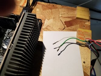
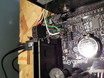
also included is an example picture showing the plug thats attached top the HP case i need to figure out a way to plug this doo hicky into my gigabyte mobo as i cant afford a new case for my retro build 24dj71v.jpg
 
No, you will have to extract the wires from the plug and insert them individually on the new motherboard front panel pin block. I have run into this many times when reusing OEM cases. Just keep in mind that the colored wire if each pair needs to go on the "+" pin. Follow them back to their source and then put labels on them with some masking tape.

Often the OEM wire harness is too short to each the new motherboard front panel pin block. In that situation I splice additional wire into each lead. It's a pain but no other way. You can actually buy leads already made for this purpose with the plastic connector ends already on and labeled. But you still have to splice and solder. A lot of newer motherboards place the front panel pin block way of the edge of the board instead of in the corner and so the OEM case wire bundle won't reach.

https://www.cdw.com/shop/products/S...kwcid=AL!4223!3!189295083002!!!g!110611236259!
 
Last edited:
I know this after the fact but when picking MB's and cases, make sure they are compatible. In this case, just do what Trents said and you should be fine.
 
No, you will have to extract the wires from the plug and insert them individually on the new motherboard front panel pin block. I have run into this many times when reusing OEM cases. Just keep in mind that the colored wire if each pair needs to go on the "+" pin. Follow them back to their source and then put labels on them with some masking tape.

Often the OEM wire harness is too short to each the new motherboard front panel pin block. In that situation I splice additional wire into each lead. It's a pain but no other way. You can actually buy leads already made for this purpose with the plastic connector ends already on and labeled. But you still have to splice and solder. A lot of newer motherboards place the front panel pin block way of the edge of the board instead of in the corner and so the OEM case wire bundle won't reach.

https://www.cdw.com/shop/products/S...kwcid=AL!4223!3!189295083002!!!g!110611236259!

Hi Trent's, I am having the same problem as OP and I'm unsure on your instructions I have gone into more detail on my tomshardware post: http://www.tomshardware.co.uk/answers/id-3884525/front-panel-connector-mobo.html
 
The wires in the one piece OEM front panel connector have ends that are crimped metal tubes held in the one piece plastic connector block by "keepers". You must depress the keepers with a sharp tool (like a hat pin) to be able to slide the wire ends out of the one pieces block. Once you have extracted them, trace the wires back to their origin in the OEM case's front panel. This is pretty straightforward as they are color coded. Tracing them back may require you to remove the front panel of the case so as to be able to view the exact LED or button they originate from. The label the wires with masking tape: "Power btn," "HD LED," etc. The crimped sleeves on the terminal end (motherboard end) are hollow (female) and can be used by themselves (without a plastic block) to make the connection with the male pins on the new motherboards's front panel pin block, being careful not to allow them to make contact with each other in the pin block. This is usually not a problem unless the wires have a lot of horizontal stress on them.

The white or black wire of each pair is - and the colored wire is +. Usually, the + pins in the FP pin block pairs are the ones closest to the rear edge of the board. But consult your motherboard manual to make sure.

Another option is to buy a set of generic FP connector wires and splice them into the existing case FP wire harness pairs. https://www.newegg.com/Product/Prod...Doh6-XTx7hEGFr_Ih_hoCEusQAvD_BwE&gclsrc=aw.ds
 

Attachments

  • connectors_2.jpg
    connectors_2.jpg
    1.8 MB · Views: 192
  • connectors_1.jpg
    connectors_1.jpg
    1.9 MB · Views: 193
Last edited:
Update. Kaitlin, from the pic in your first post you have a different kind of "keeper" than I described. With yours, you will need to pry up the plastic tabs on plastic plug that servers as the keeper. The plastic tab catches on a the insert and prevents it from working loose. Just pry it up with a hat pin and pull on the wire.
 
Back