• Welcome to Overclockers Forums! Join us to reply in threads, receive reduced ads, and to customize your site experience!

[O/C]Load Line Calibration and You

Overclockers is supported by our readers. When you click a link to make a purchase, we may earn a commission. Learn More.

Overclockers.com

Member
Joined
Nov 1, 1998
Last edited by a moderator:
Excellent article Bnova! Informative!

One thing I didnt see (if I missed it I apologize) is the flip side of using LLC is that under moderate/light loads where the the LLC isnt active/compensating for vdroop it could potentially cause reboots/failures due to not enough voltage being supplied to the CPU in an idle or light load state. This condition becomes more apparent when LLC is enabled and the load voltage goes UP (vRaise?) as opposed to keeping the idle/set voltage and the user lowers the voltage in the bios to compensate.

I would, and do still use it, however I enable it after I have my overclock set and stable. Sometimes, albeit it rare, LLC/Vdroop control has been known to cause instability in some situations.

I am trying simply regurgitate some things I remember, if I am mistaking, please let me know... :) :chair:
 
I agree with EarthDog. Can we see some results going from idle to full load? That is usually where the spike occurs. Besides that, very well done.
 
The problem as I understood it is simply in the user compensating too much for the spike (as in goes above idle voltages) that does occur with LLC. The spike is there, its just the user trying to make it the same as the idle voltage is where this problem comes in to play.
 
I kept watch for spikes when the load hit as well, nothing there either.

I haven't seen any odd vcore with LLC enabled at light load unless I've had EIST and/or C1E enabled, in which case vcore in any situation is anybodies guess.

I had fun doing this, when I have a 1156 setup again I'll test it, as well.
 
Maybe I wasnt clear...

Its not an 'odd vcore' its that people tend to compensate for the overvoltage LLC gives you on load and they lower the vcore to compensate causing instability at idle/low loads. I wouldnt imagine this happening to those in the know, but to others as I have seen it happen.
 
Last edited:
Ahh ok, that makes sense. I haven't run into that personally, but my board doesn't gain a whole lot.
 
Maybe its just the 'noobs' then? I havent run into this issue either, but then again, I dont touch the vcore after LLC is enabled either later in my 24/7 stabel o/c process.

Again, great article and dont think I was picking at it either. :)
 
Oh I don't mind. I ask plenty of annoying questions myself, I'm happy to answer other people's questions.
 
Nice to see some real investigation into this. But if I had to guess I'd say there's a very good possibility that the voltage spikes are <50us. When you say your scope "refresh rate" is 50us, do you mean your scope takes a sample every 50us (i.e. 20 kSamples/s)? Or that each time division is 50us? In either event, that's probably too slow to see a voltage spike that occurs on a nanosecond scale. I have some nice scopes at work that can go down to nanoseconds, but getting a computer in here to test them would be rather difficult.

I chatted with a co-worker who has experience in power supplies and this is what we came up with as far as the voltage spikes go: it is far more likely to see a large spike going from heavy to light loads as opposed to light to heavy. Switching regulators on a motherboard have a feedback loop that makes sure the voltage is what its "supposed" to be. When the load increases, the feedback loop has a fixed slew rate that determines how fast it can react, and it will definitely be slower than the time it takes to go from a light load to a heavy load. The light-to-heavy spike comes from an overshoot in the feedback loop where it continues ramping the power up beyond what is necessary to maintain the voltage. But the feedback loop keeps chugging along and brings it back to normal very shortly after.

The voltage spike going from heavy-to-light is worse. Switching regulators work by storing energy in an inductor then passing it to the load. The output voltage is controlled by the duty cycle of a pulse-width-modulation signal used to do the switching. If the current goes beyond a certain limit, that voltage will start to droop because energy isn't being transferred fast enough. The solution is to increase the duty cycle to supply extra current. But if all of a sudden you drop the current draw (going to light load), the duty cycle is still longer, and since the regulator isn't strained the voltage will spike. The feedback loop comes into effect and lowers the duty cycle, but you'll still see a large spike before it reaches equilibrium.
 
Kayson, I think this article started from what happens in theory compared to what can be proven and tested for in application on actual hardware with a reasonable attempt at observing the theoretically expected behavior. Your comment while informative and well stated, brings us full circle - Yay for symmetry! :D
 
Last edited:
Oh I got the point of the article. I'm just providing some more theory as to what should be seen and suggesting that someone take a look with a higher-speed scope just to be sure.
 
I agree, it'd be nice to use a finer grade scope with this, if this article can inspire someone to do that I will be very pleased.

Thanks for the details on how the power supply works, too.
 
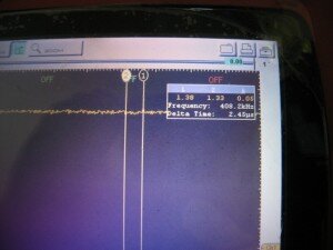
Inspected the scope carefully, for those who care:
50uS per screen (50 microseconds), the finest point it can detect/display appears to be 90-120 nanoseconds, somewhere in that area.

And you're welcome!
 
Kayson would be correct in his description of how the switch mode setup should work. Part of where the spike could come from is that time lapse between the cpu going from full load to light load in a matter of cpu cycles. Now if that really happened then the cpu PSU (the switch mode parts you are testing) would have a cycle time much longer and potentially supply a dangerous voltage.

If your scope is measuring around 100 ns, that would be roughly a 10 Mhz signal. That should be fine even for a cpu psu. (I don't know the frequency that the switching signal runs, but I'd think it would be in the 1-5 Mhz area.)

I would think that a large part of this issue might deal more with the feedback circuit than the actual regulation itself. Most of the capacitors and inductors are sized to meet a goal load/regulation requirement. The capacitors would need to store enough juice to be able to go from light to heavy load quickly, but that size should be able to handle ripple in the sub 1 volt category easily.

I'd suspect if this issue is ever verified I would think the likely cause would be a poorly implemented feedback circuit (yeah I already said that, but.) Most of these are based on programmable switch mode supply control ics. It's likely someone did a poor job of implementing the over voltage detection, and is just letting the unit cycle and use the feedback loop like normal. Most of these chips should have a dedicated over volt input which should cause the circuit to cycle preventing an over volt situation. (Kind of like applying the brakes while cruise control is on, it disables and you stop.)

That's just my theory based on my experience with larger scale switch mode ic chips.
 
Back